How a transformer works
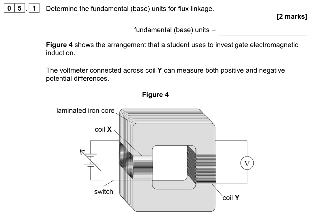
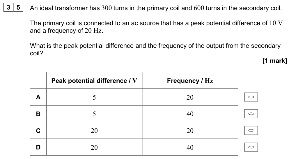
A transformer changes the size of an alternating p.d. It has two coils, the primary ($N_p$ turns) and the secondary ($N_s$ turns), wound on a shared soft iron core.
- An alternating current in the primary coil produces an alternating magnetic flux in the core.
- The core links this changing flux to the secondary coil.
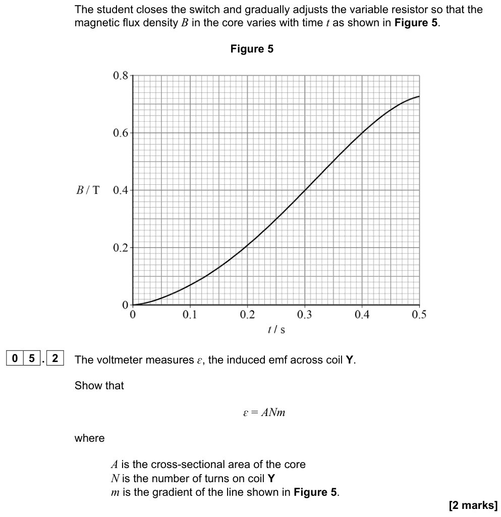
- The changing flux linkage in the secondary induces an alternating e.m.f. (Faraday's law) of the same frequency.
A transformer does not work with steady d.c., because a constant current gives a constant flux and no induced e.m.f.
The transformer equation
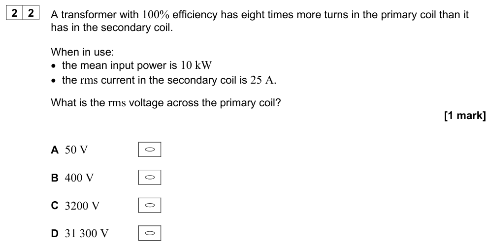
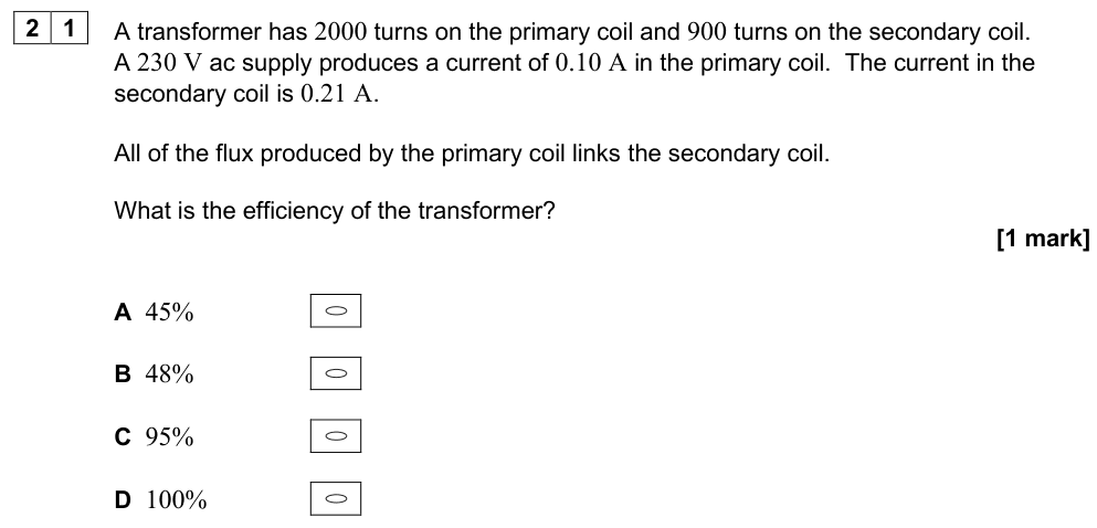
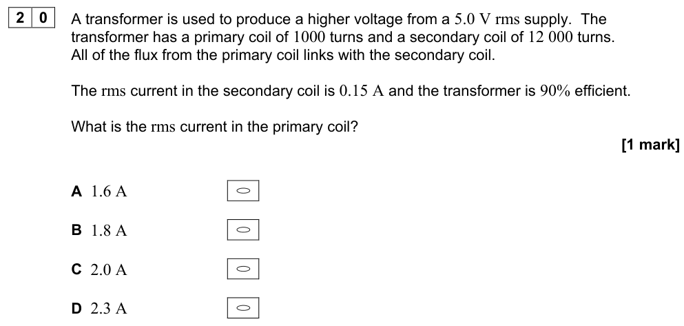
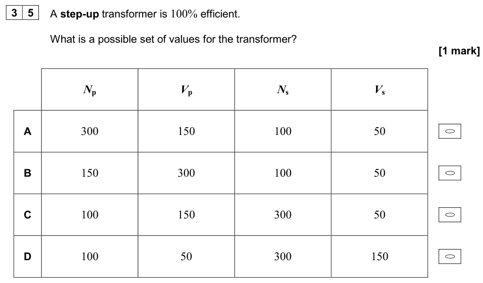
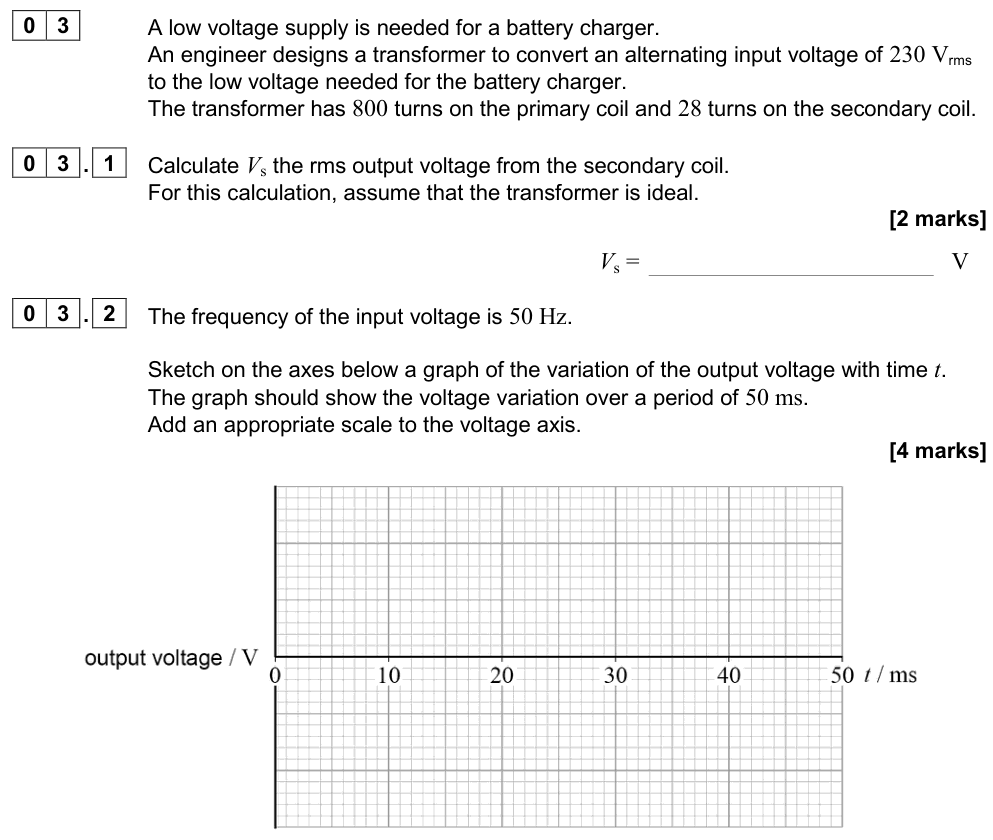
$$\frac{N_s}{N_p} = \frac{V_s}{V_p}$$
- Step-up transformer: $N_s > N_p$, so $V_s > V_p$.
- Step-down transformer: $N_s < N_p$, so $V_s < V_p$.
Efficiency
Transformer efficiency
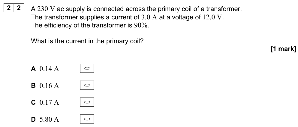
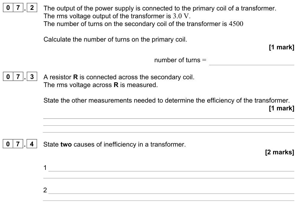
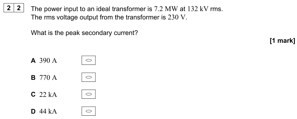
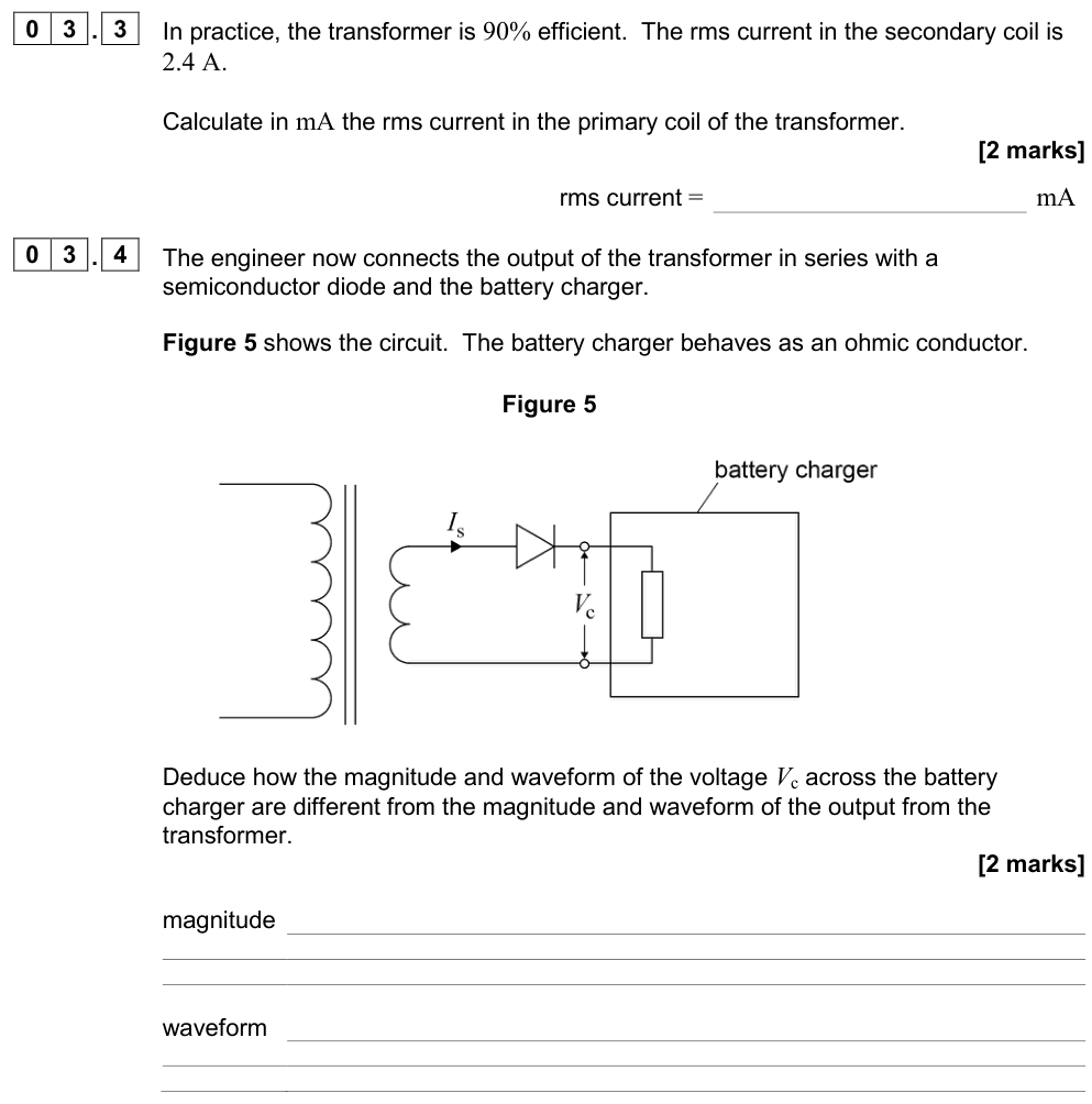
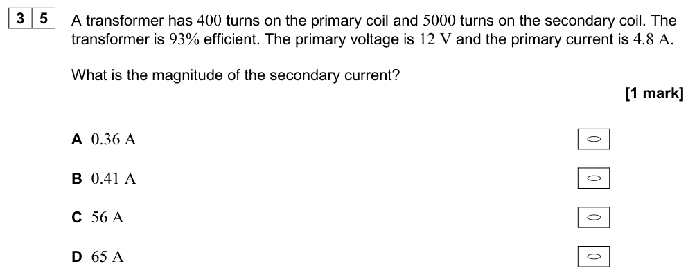
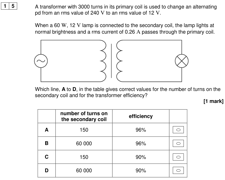
$$\text{efficiency} = \frac{\text{output power}}{\text{input power}} = \frac{I_sV_s}{I_pV_p}$$
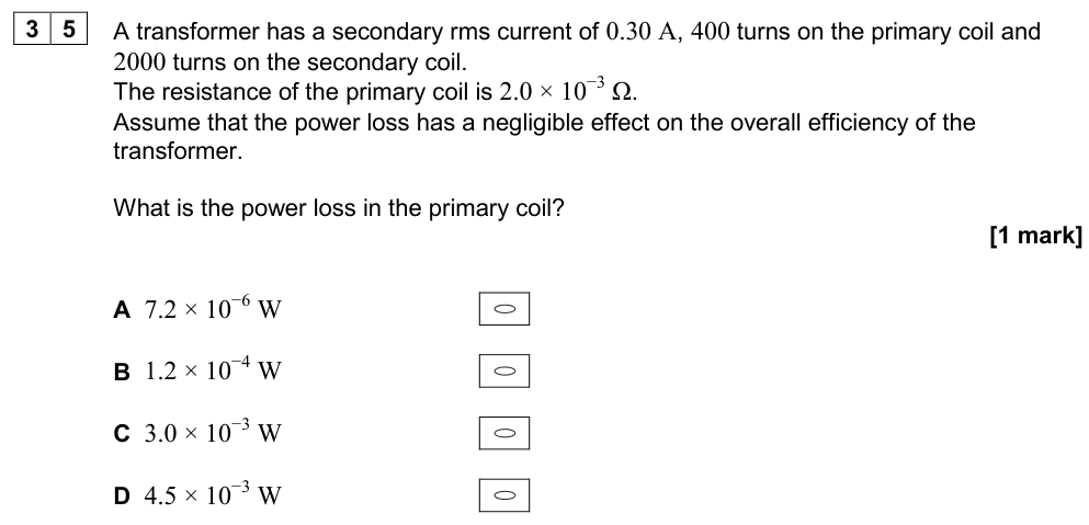
For an ideal (100% efficient) transformer $I_sV_s = I_pV_p$, so $\dfrac{I_s}{I_p} = \dfrac{N_p}{N_s}$: a step-up transformer steps the current down by the same factor.
Worked example
A transformer has 1200 primary turns and 60 secondary turns and is connected to 230 V mains. A 12 V lamp drawing 2.0 A is connected to the secondary.
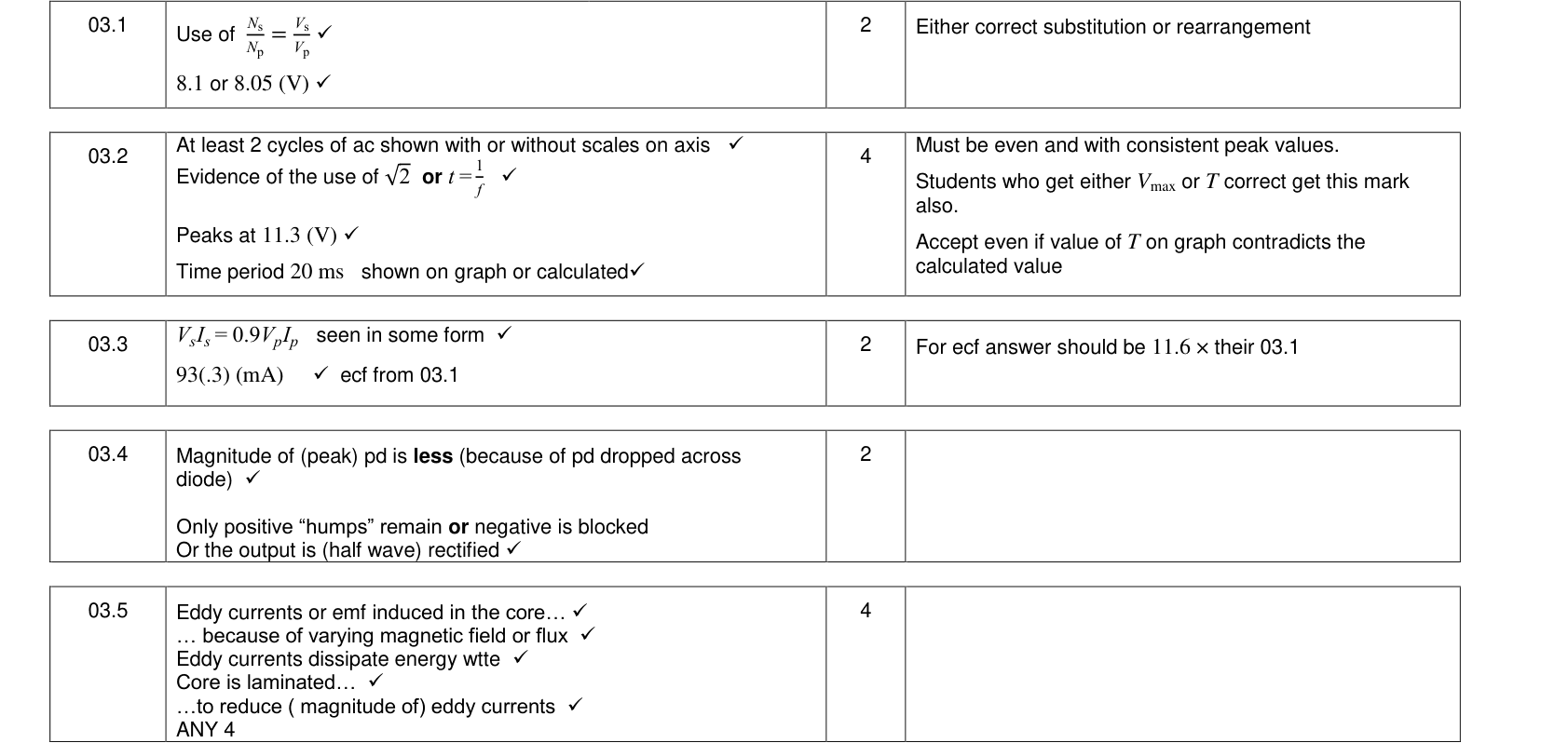
$V_s = 230 \times \dfrac{60}{1200} = 11.5\ \text{V}$.
If the transformer is 92% efficient and supplies 24 W: input power $= 24/0.92 = 26\ \text{W}$, so $I_p = 26/230 = 0.11\ \text{A}$.
Causes of inefficiency
| Loss | Cause | How it is reduced |
|---|---|---|
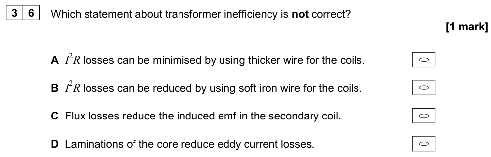
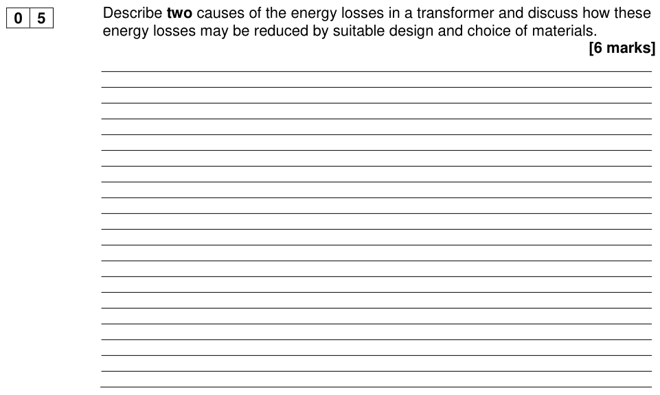
| Copper (resistive) losses | heating ($I^2R$) in the resistance of the coils | use thick, low-resistance copper wire (especially for the high-current coil) |
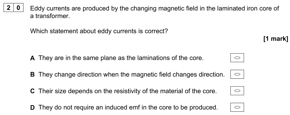
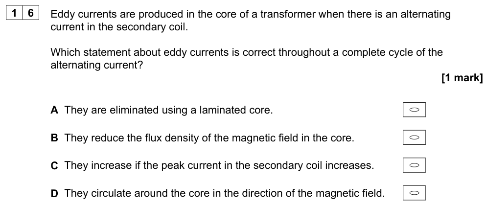
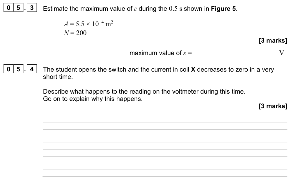
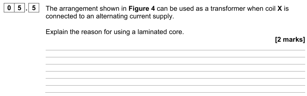
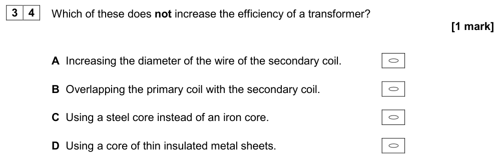
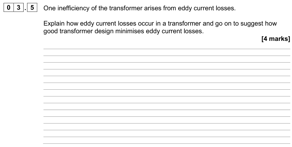
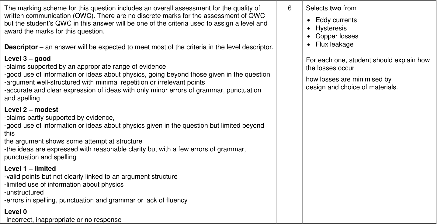
| Eddy currents | the changing flux induces currents in the iron core, which heat it | laminate the core: thin insulated sheets break up eddy current paths |
| Hysteresis losses | energy is needed to magnetise, demagnetise and reverse the magnetisation of the core every cycle | use a soft magnetic material (e.g. soft iron, silicon steel) that is easily magnetised and demagnetised |
| Flux leakage | not all the flux from the primary links the secondary | design the core so the coils are wound close together (e.g. one on top of the other) |
Well-designed transformers can be over 99% efficient.
Required practical 7: efficiency of a transformer
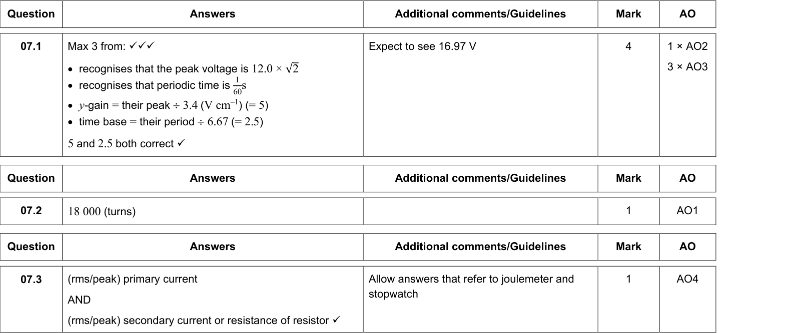
Connect the primary coil of a transformer (e.g. two C-cores or a demountable transformer) to a low-voltage a.c. supply, with an ammeter and voltmeter to measure $I_p$ and $V_p$. Connect a variable resistor (load) to the secondary with an ammeter and voltmeter for $I_s$ and $V_s$ (use a.c. meters, which read r.m.s. values).
Calculate efficiency $= \dfrac{I_sV_s}{I_pV_p}$ for a range of load currents. Investigate the effect of changing the core (laminated vs solid, closing the core completely, separating the C-cores) and of the load current. The efficiency usually falls at high currents as $I^2R$ losses increase.
Safety: use low voltages; switch off before changing connections; the core can get warm.
High-voltage transmission
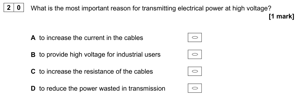
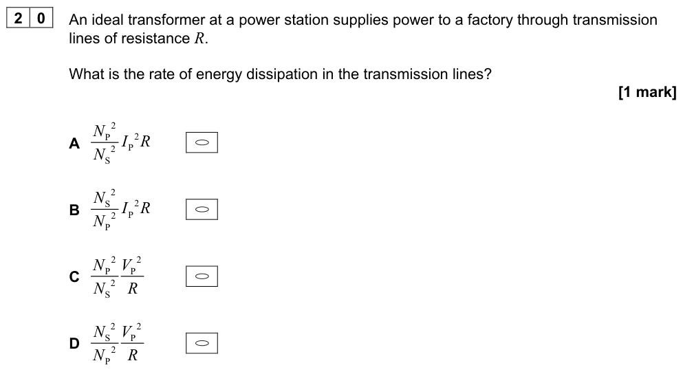
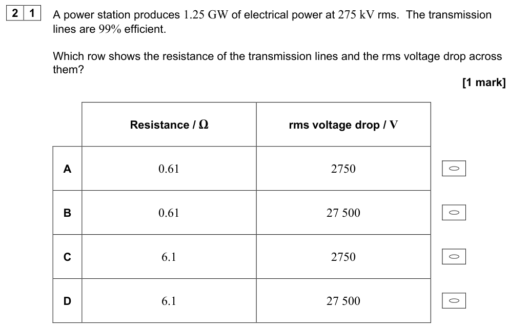
Electrical power is generated in power stations, sometimes far from where it is used. It is sent along transmission lines (cables), which have resistance $R$. The power lost as heat in the cables is
$$P_{\text{loss}} = I^2R$$
For a given power $P = IV$ transmitted, a higher transmission voltage means a smaller current $I = P/V$, and so a much smaller power loss:
$$P_{\text{loss}} = \left(\frac{P}{V}\right)^2R \propto \frac{1}{V^2}$$
Increasing the voltage by a factor of 10 reduces the current by 10 and the power loss by 100. This is why electricity is transmitted at very high voltages (e.g. 132–400 kV): step-up transformers at the power station increase the voltage, and step-down transformers at substations reduce it for safe use in homes and industry. This only works with a.c., which is one reason the grid is a.c.
Worked example: transmission losses
A power station sends 20 MW through cables of total resistance 5.0 Ω.
At 25 kV: $I = 20 \times 10^{6}/25 \times 10^{3} = 800\ \text{A}$; $P_{\text{loss}} = 800^2 \times 5.0 = 3.2\ \text{MW}$ (16% lost). The voltage drop along the cables is $IR = 4000$ V.
At 400 kV: $I = 50\ \text{A}$; $P_{\text{loss}} = 50^2 \times 5.0 = 12.5\ \text{kW}$ (0.06% lost); voltage drop $= 250$ V.
Common mistake
When calculating the power lost, use $I^2R$ with the current in the cable and the cable resistance, or $V^2/R$ with the voltage drop across the cable, not the transmission voltage. $V_{\text{transmission}}^2/R$ gives a nonsense answer.
Summary
- Alternating current in the primary → alternating flux in the core → induced alternating e.m.f. in the secondary.
- $N_s/N_p = V_s/V_p$; efficiency $= I_sV_s/I_pV_p$; ideal: $I_s/I_p = N_p/N_s$.
- Losses: coil resistance (thick wire), eddy currents (laminated core), hysteresis (soft iron), flux leakage (good core design).
- Transmission: $P_{\text{loss}} = I^2R$; high voltage → low current → much lower losses.