The potential divider
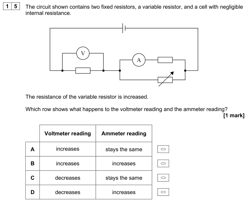
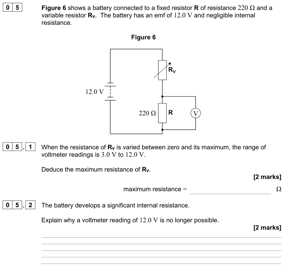
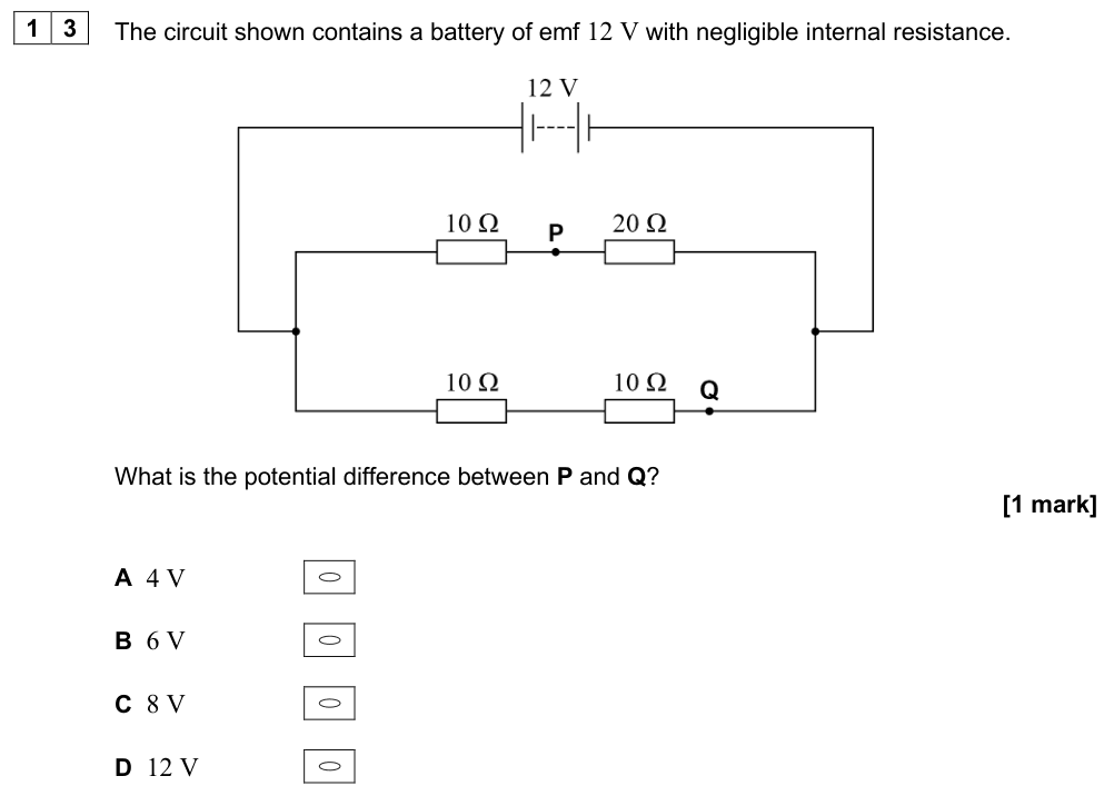
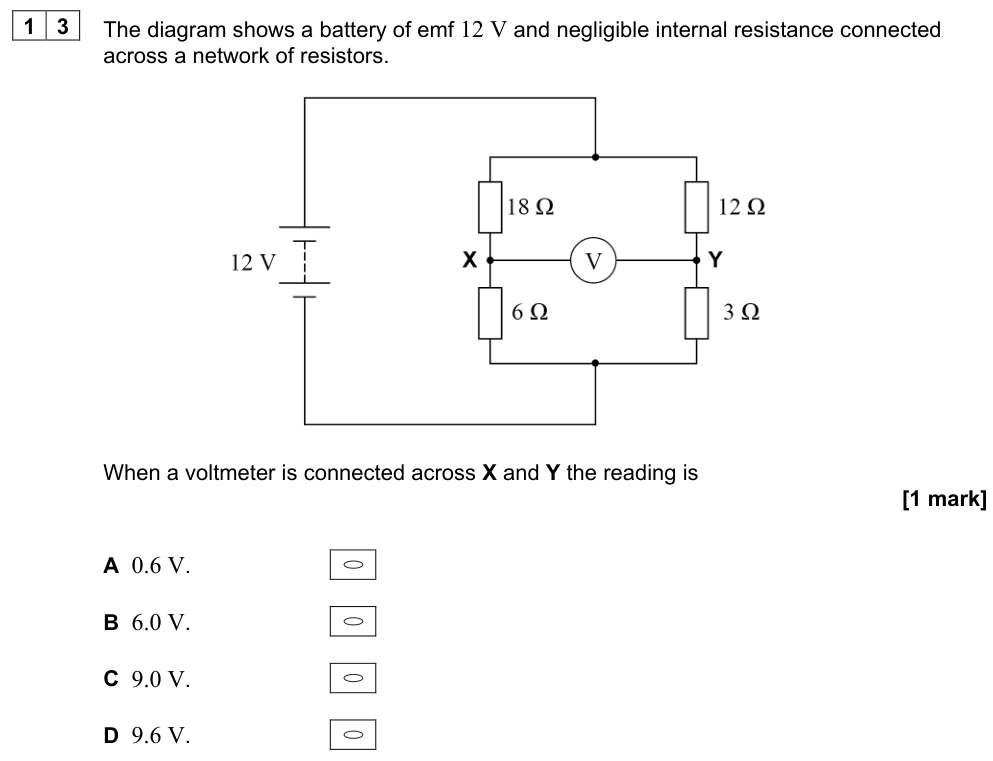
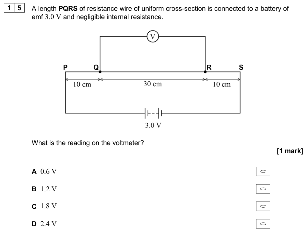
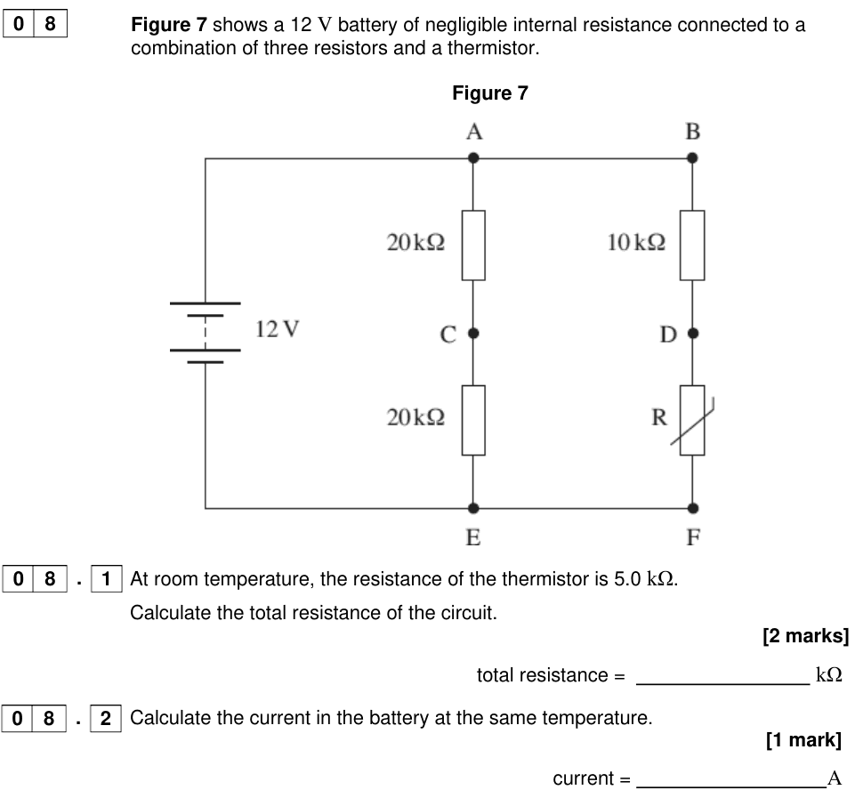
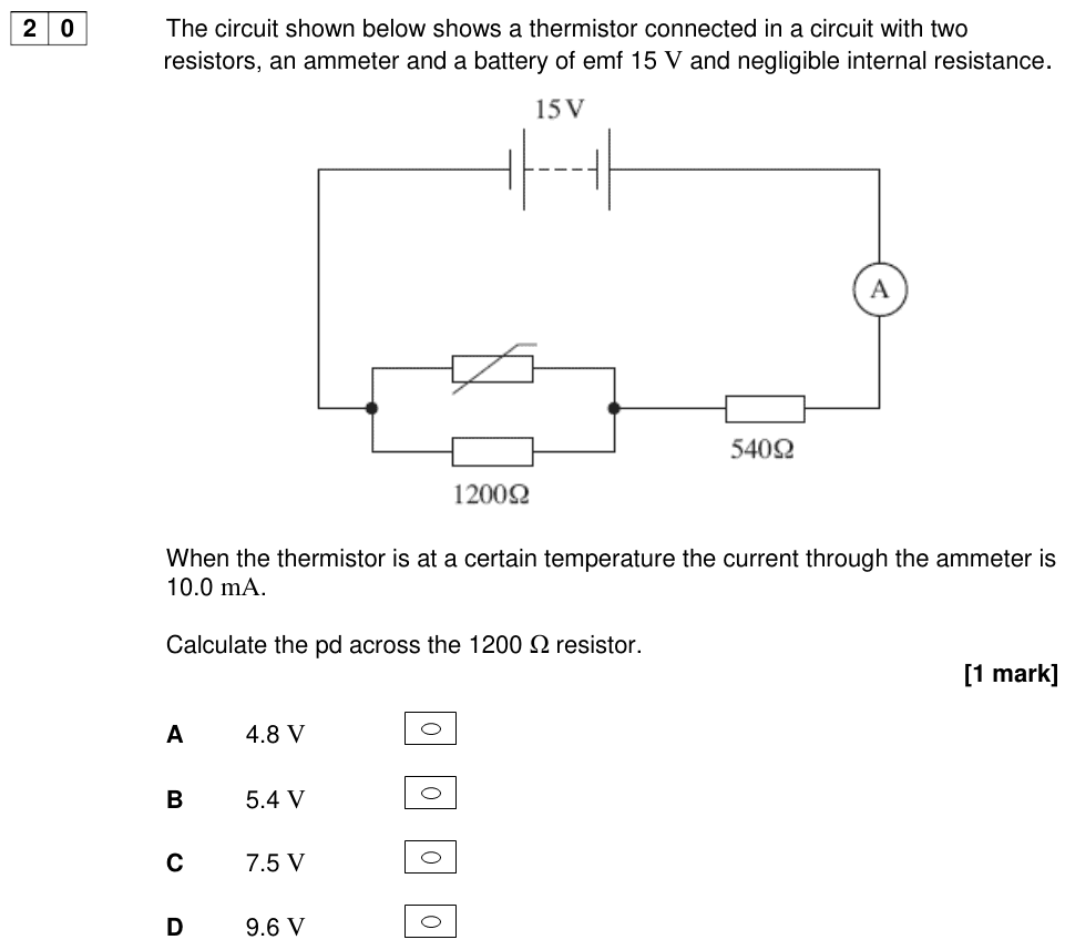
A potential divider is two (or more) resistors in series across a supply. The supply p.d. is shared between them in proportion to their resistances, so the circuit can provide a fixed fraction of the supply p.d., or a variable p.d.
Potential divider equations
The same current flows through both resistors, so the p.d.s are in the ratio of the resistances:
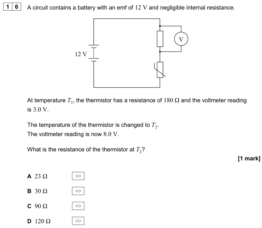
$$\frac{V_1}{V_2} = \frac{R_1}{R_2} \qquad\qquad V_{\text{out}} = V_{\text{in}} \times \frac{R_2}{R_1 + R_2}$$
Derivation: $I = \dfrac{V_{\text{in}}}{R_1 + R_2}$ and $V_{\text{out}} = IR_2$.
Worked example
$V_{\text{in}} = 12\ \text{V}$, $R_1 = 4.7\ \text{k}\Omega$, $R_2 = 2.2\ \text{k}\Omega$. $V_{\text{out}} = 12 \times \dfrac{2.2}{6.9} = 3.8\ \text{V}$.
Exam tip
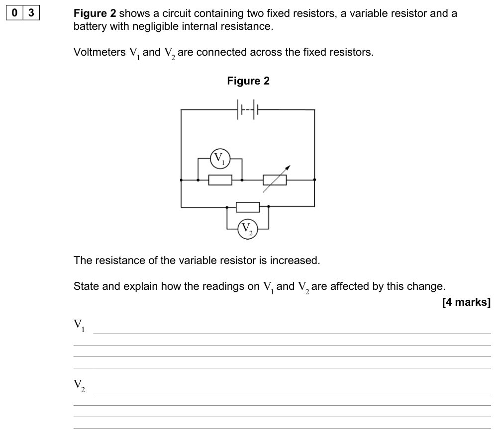
The larger resistor always has the larger share of the p.d. If you increase $R_2$, $V_{\text{out}}$ (across $R_2$) increases. If you increase $R_1$, $V_{\text{out}}$ decreases.
Variable p.d.: the variable resistor and the rheostat-as-divider
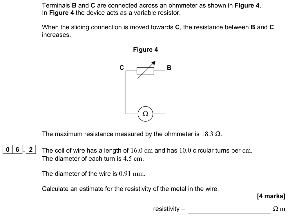
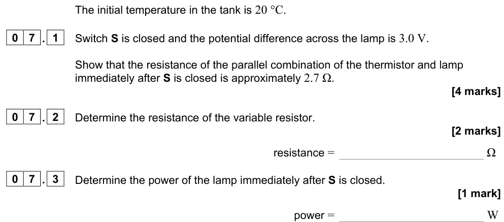
- If one of the resistors is a variable resistor, $V_{\text{out}}$ can be adjusted.
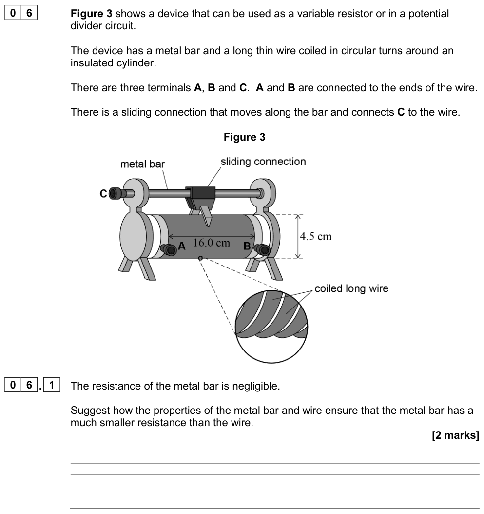
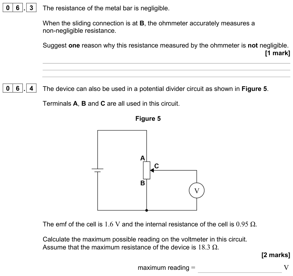
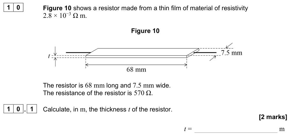
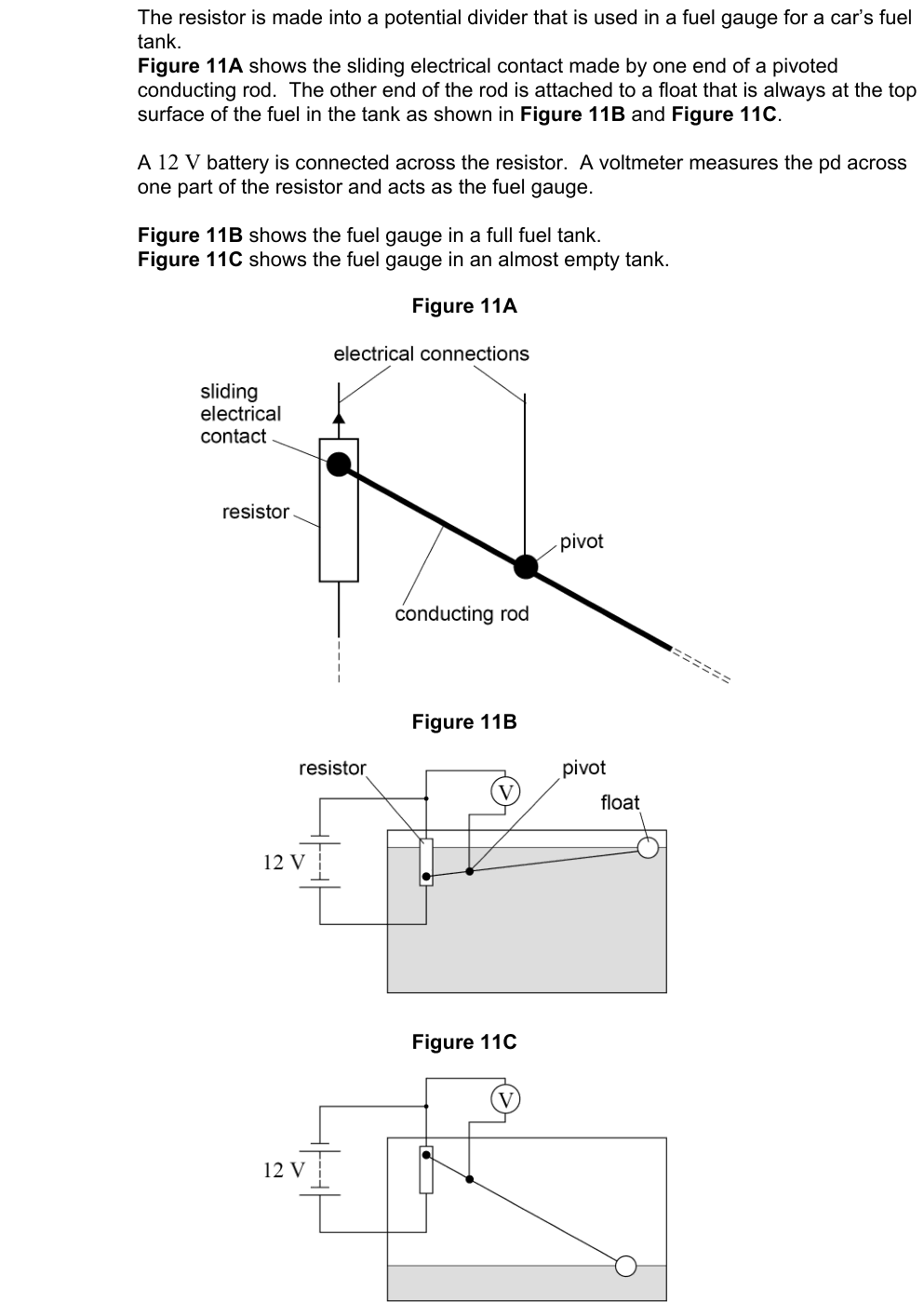
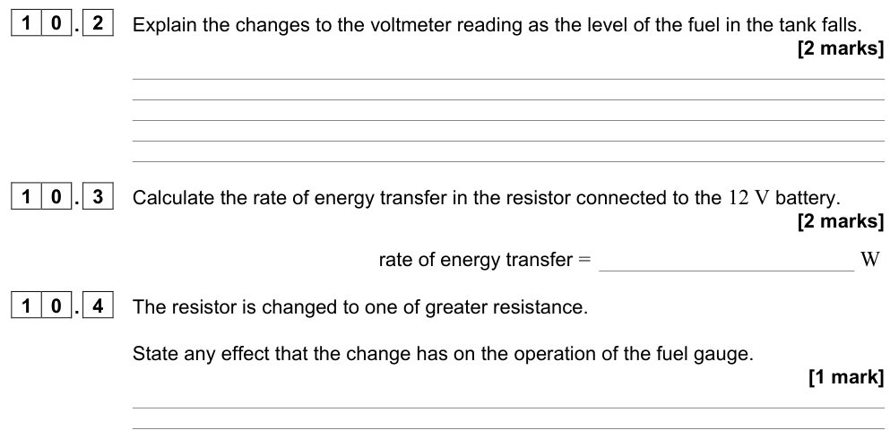
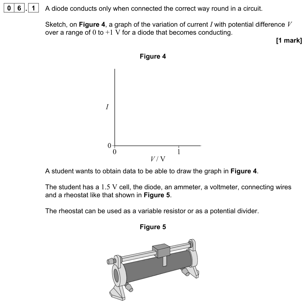
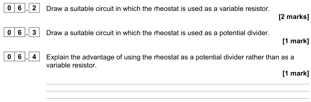
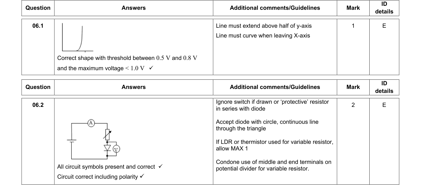
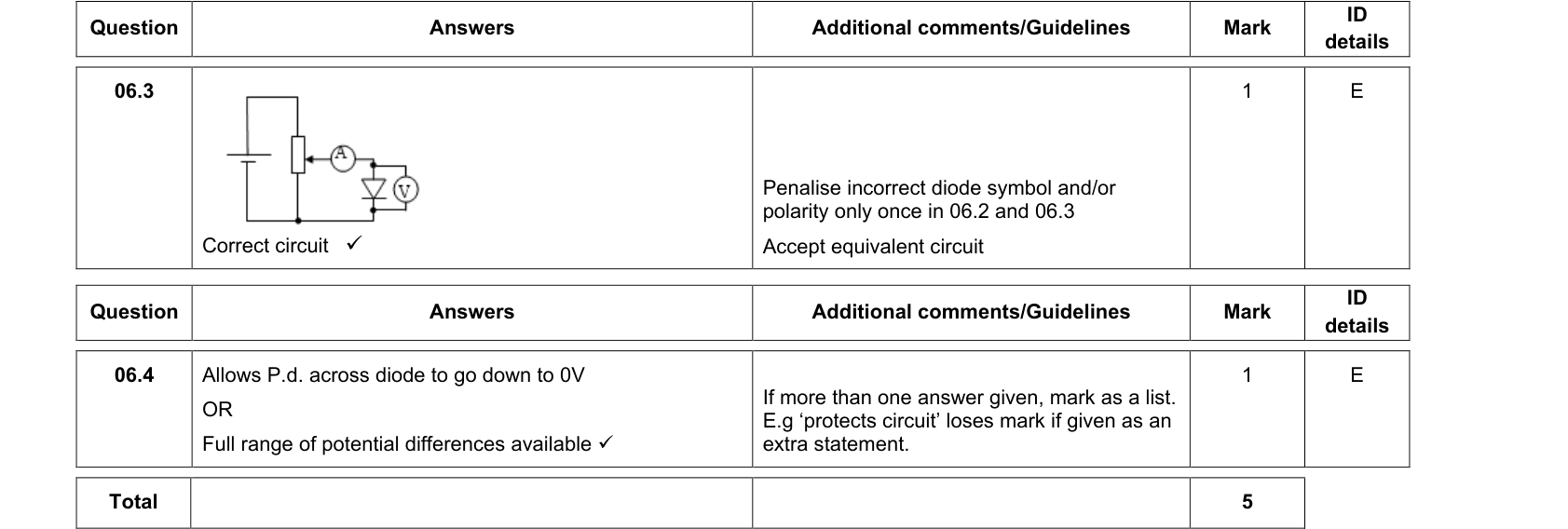
- A rotary or sliding potentiometer used as a potential divider (three terminals: the two ends across the supply and the slider as the output) gives an output that can be varied smoothly from 0 V up to the full supply p.d. This is how the p.d. across a component is varied to plot an I–V characteristic, including values close to zero.
(Using a potentiometer as a precision measuring instrument is not required.)
Sensor circuits
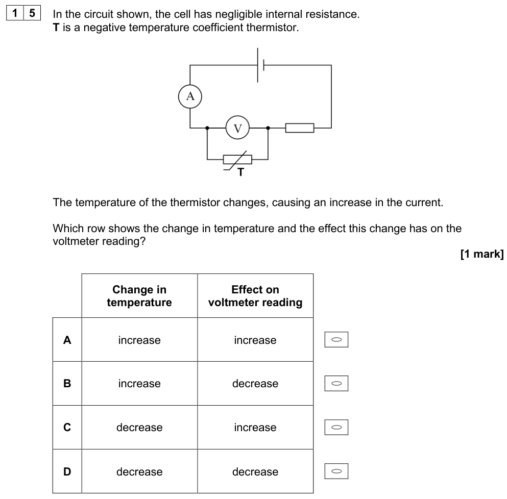
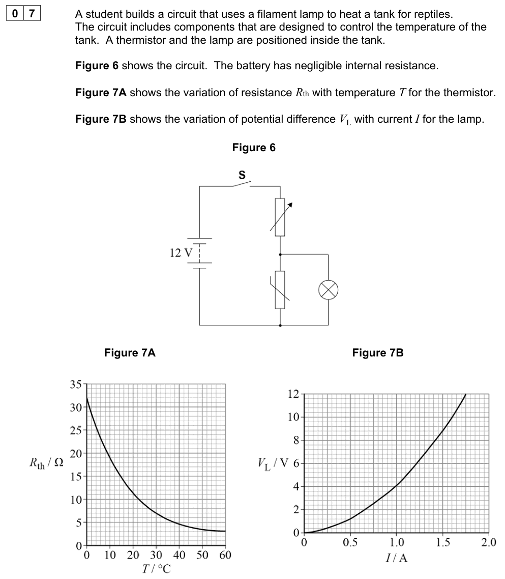
Replacing one resistor with a sensor whose resistance depends on the surroundings gives an output p.d. that responds to changes in conditions.
Light-dependent resistor (LDR)
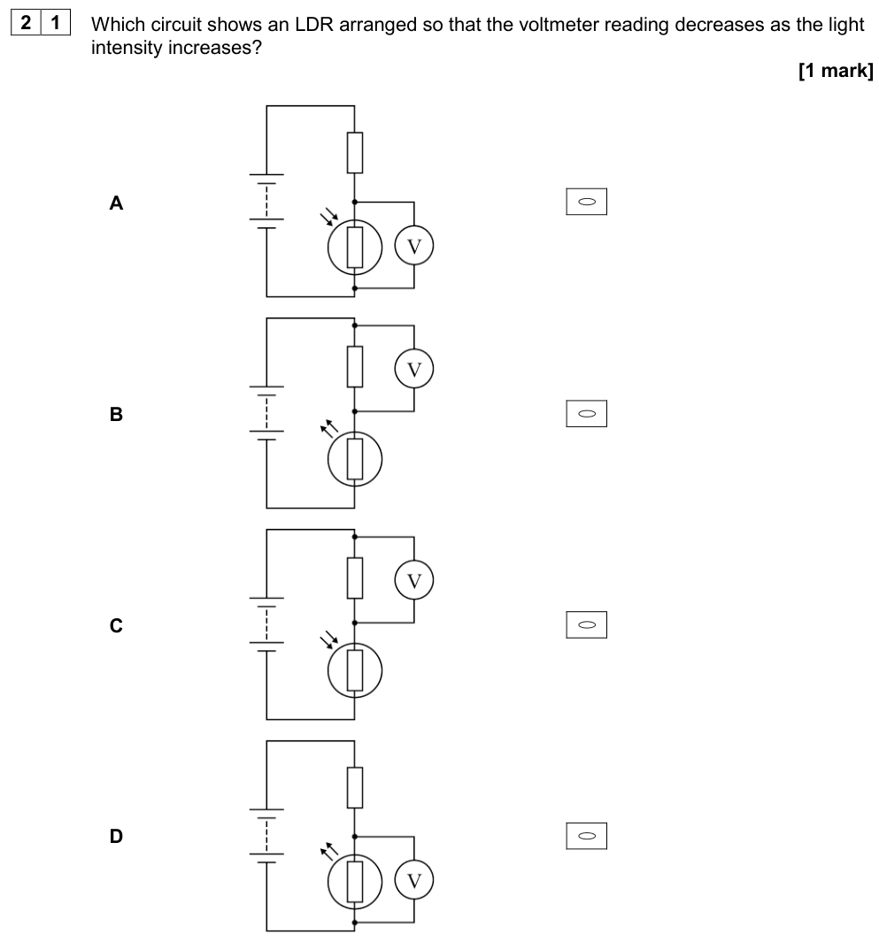
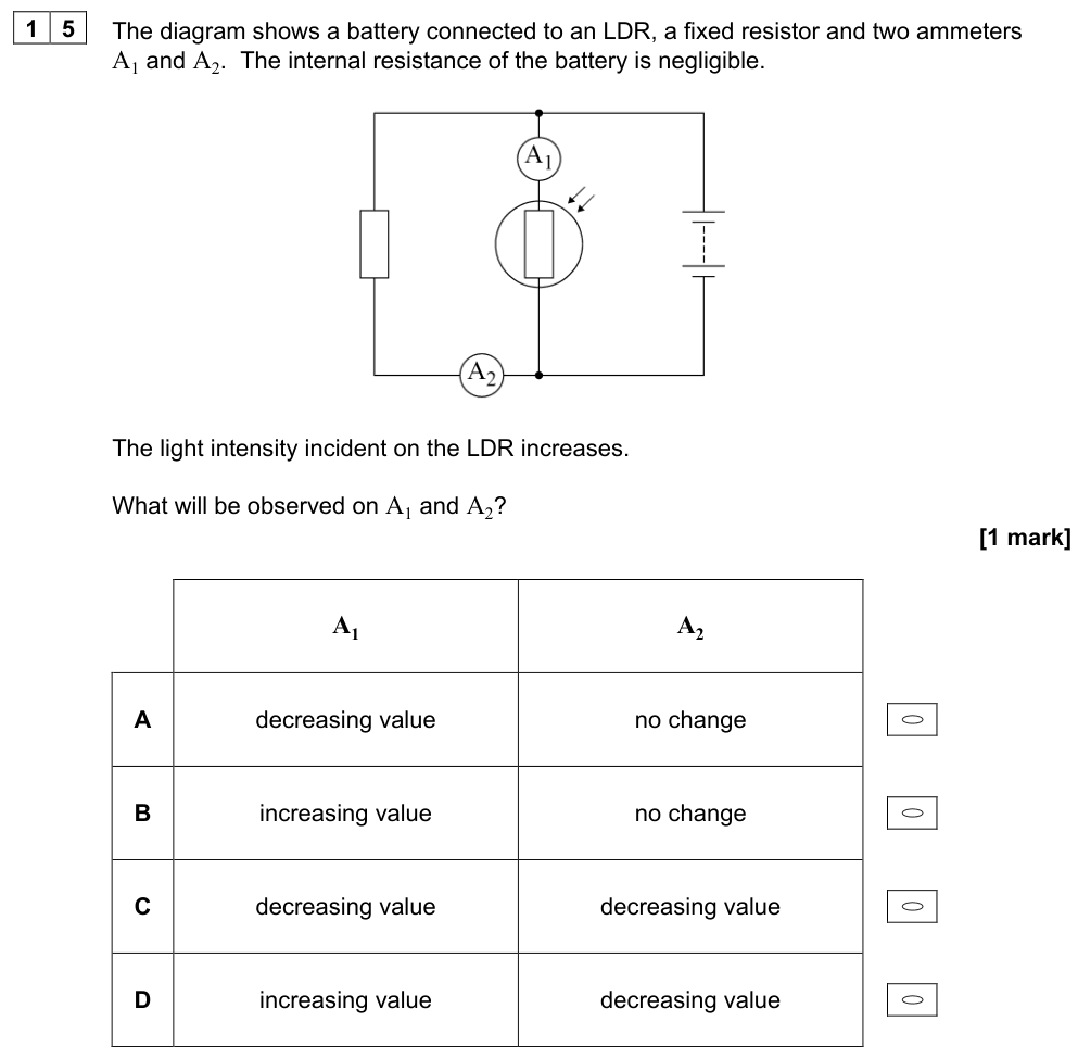
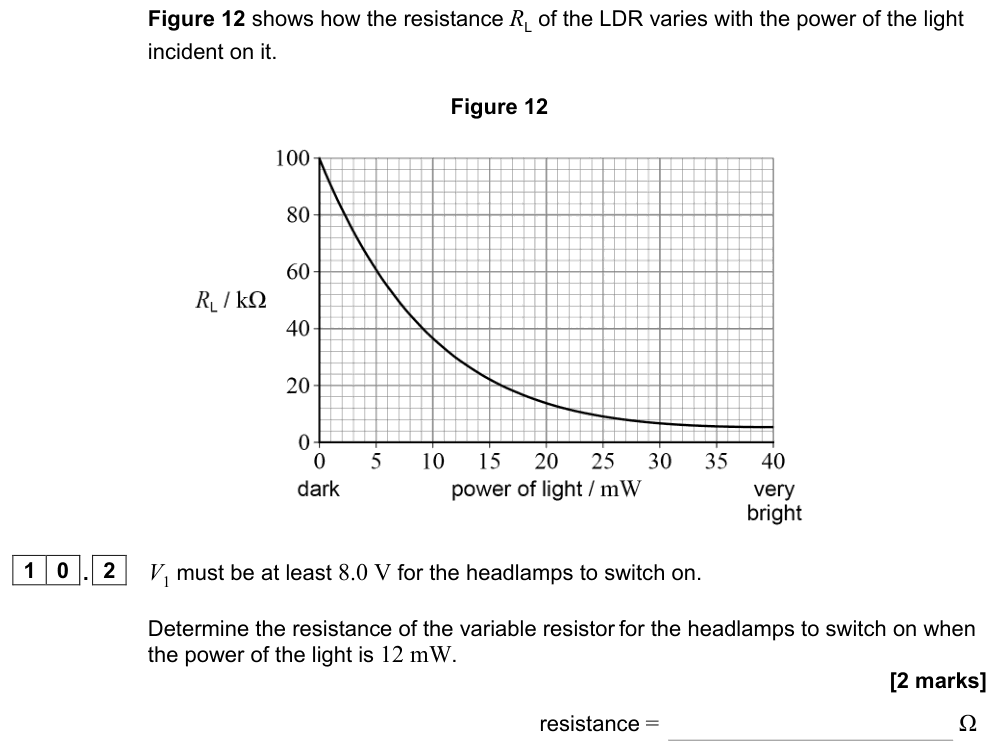
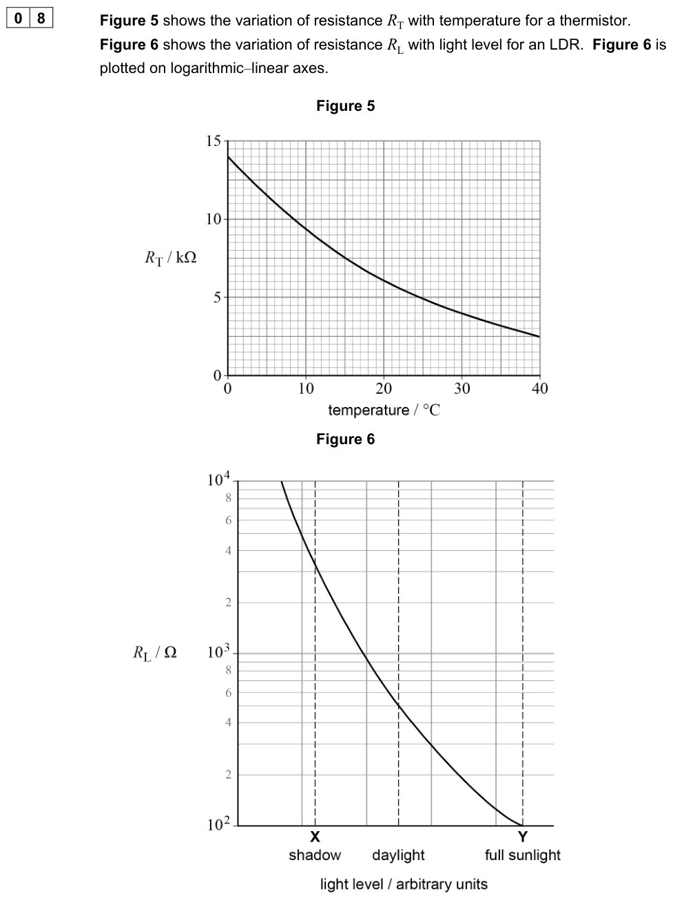
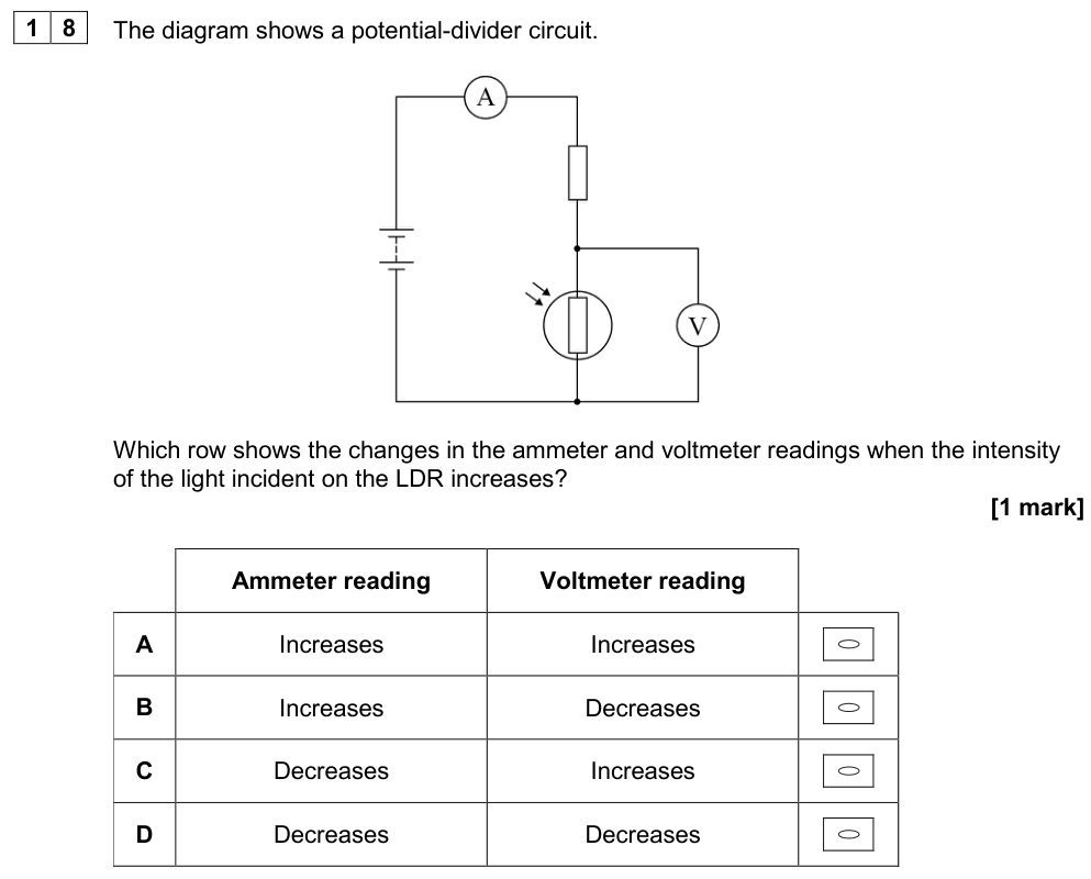
The resistance of an LDR decreases as the light intensity increases (more light releases more charge carriers).
NTC thermistor
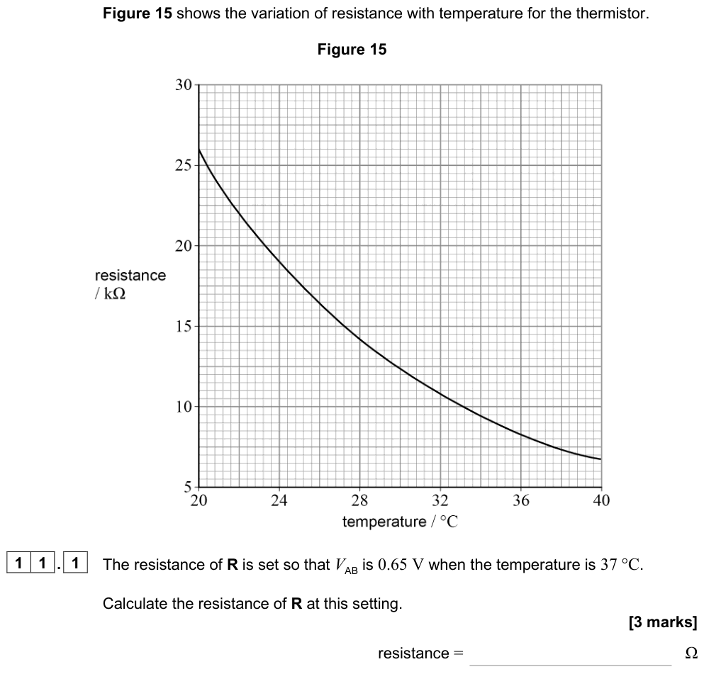
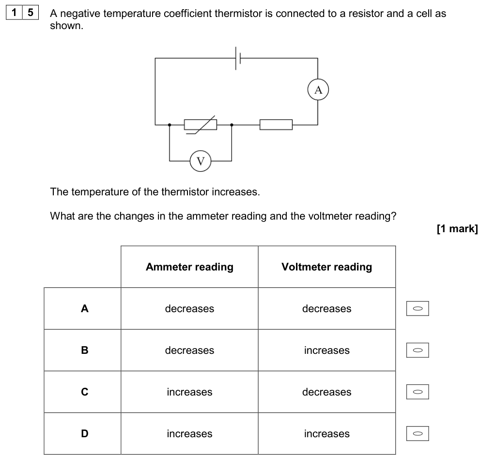
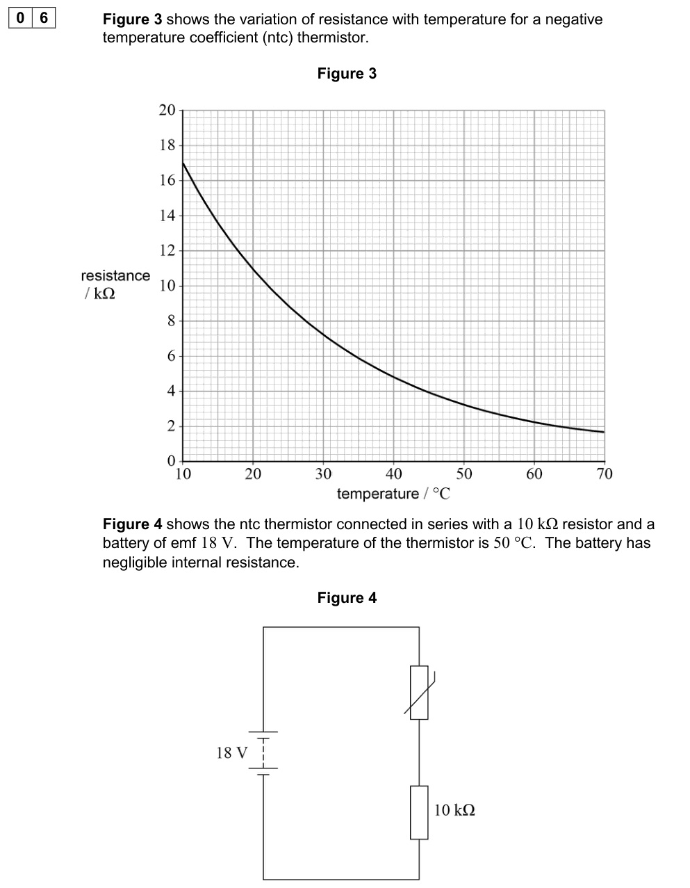
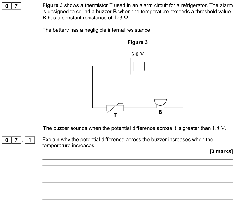
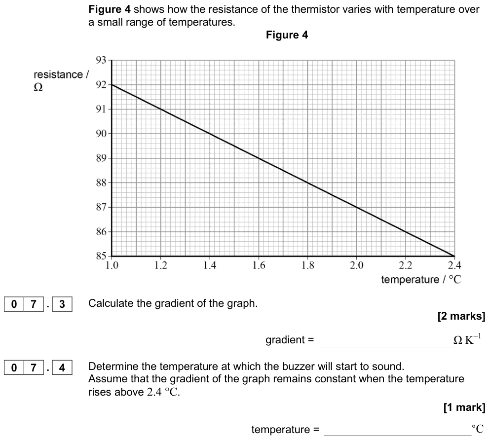
The resistance of an NTC thermistor decreases as the temperature increases.
Worked example: automatic street light
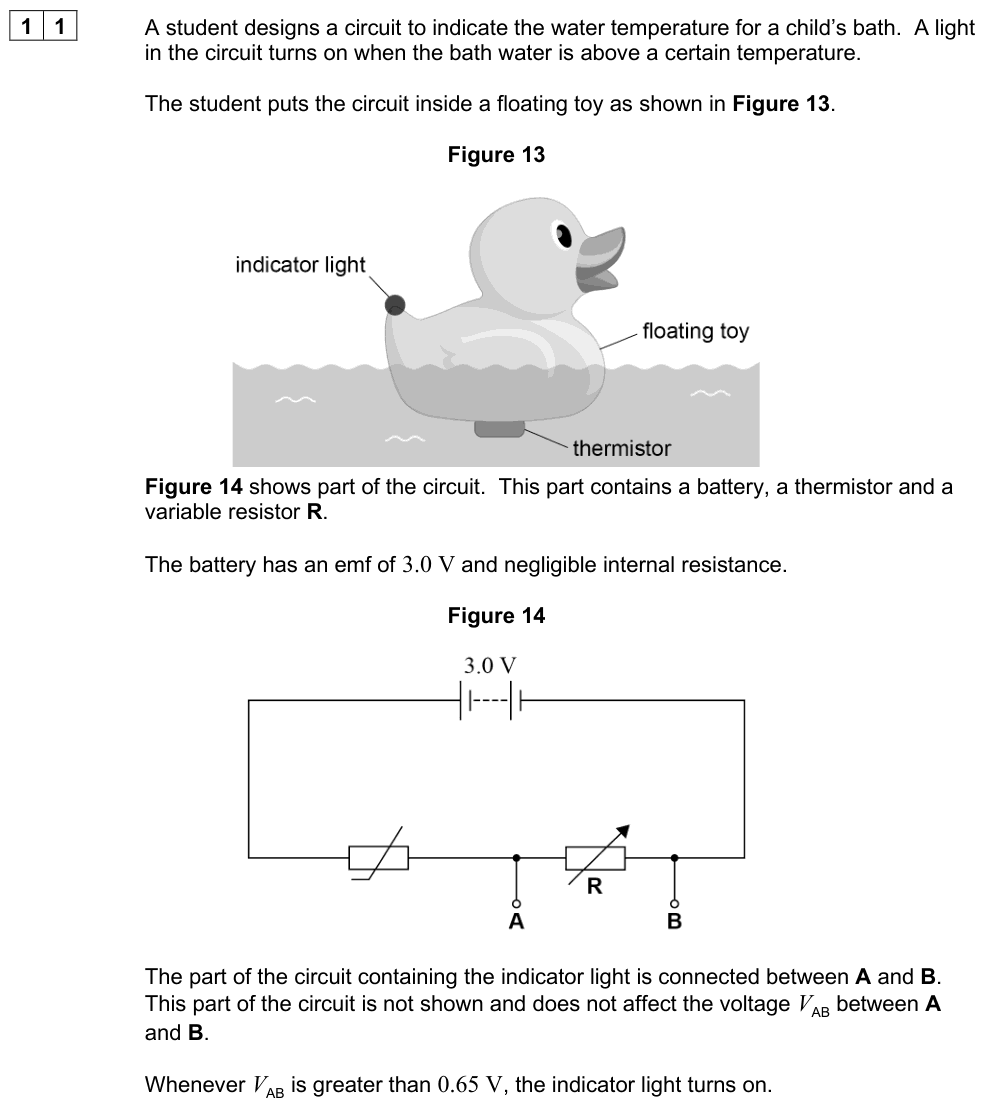
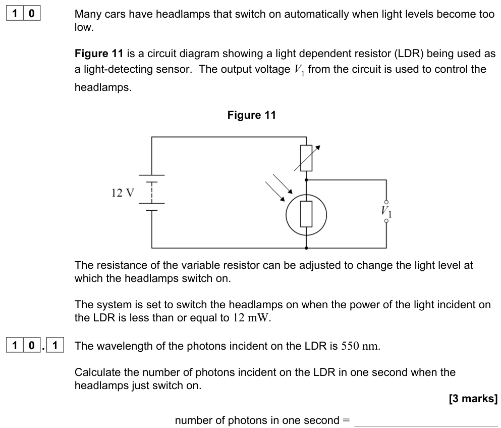
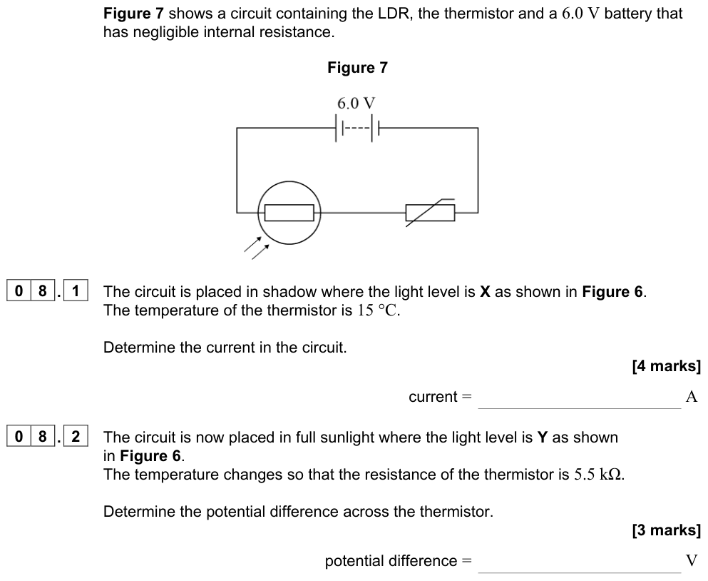
An LDR is placed in position $R_1$ (top) and a fixed resistor in position $R_2$ (bottom), with $V_{\text{out}}$ across the fixed resistor.
When it gets dark, the LDR's resistance increases, so it takes a bigger share of the supply p.d. The p.d. across the fixed resistor, $V_{\text{out}}$, decreases.
To make $V_{\text{out}}$ rise when it gets dark (to switch a lamp on), swap the positions so that $V_{\text{out}}$ is taken across the LDR.
Worked example: fire alarm
A thermistor (resistance 5.0 kΩ at room temperature, 0.50 kΩ when hot) is in series with a 2.0 kΩ resistor across a 9.0 V supply. $V_{\text{out}}$ is across the fixed resistor.
Room temperature: $V_{\text{out}} = 9.0 \times \dfrac{2.0}{7.0} = 2.6\ \text{V}$. Hot: $V_{\text{out}} = 9.0 \times \dfrac{2.0}{2.5} = 7.2\ \text{V}$. The rise in $V_{\text{out}}$ can trigger an alarm.
Choosing the fixed resistor
For the greatest sensitivity around a particular condition, choose a fixed resistor with a resistance similar to that of the sensor in that condition. The output then changes most for a small change in the sensor's resistance.
Loading a potential divider
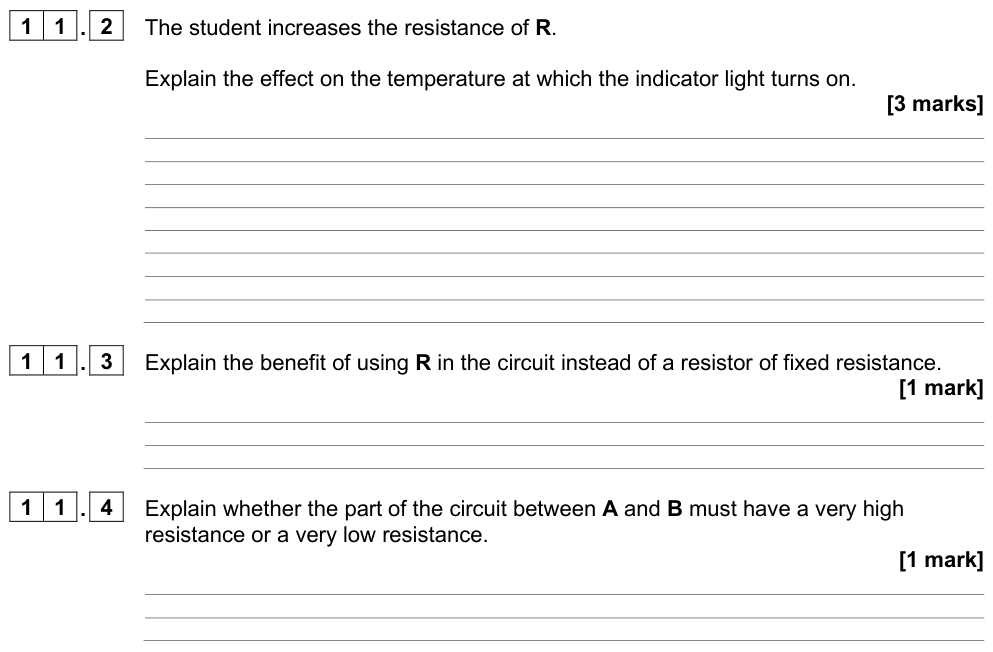
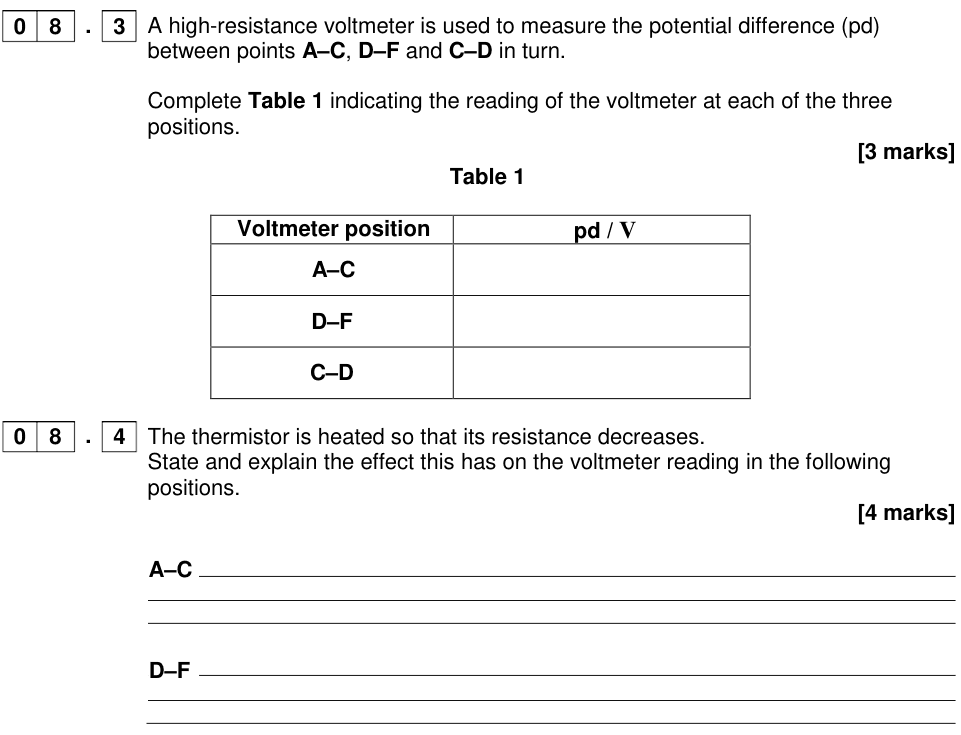
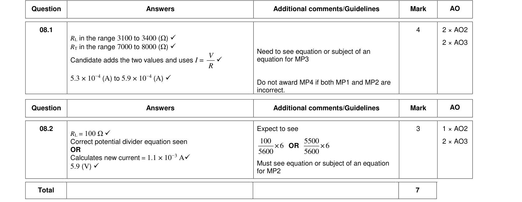
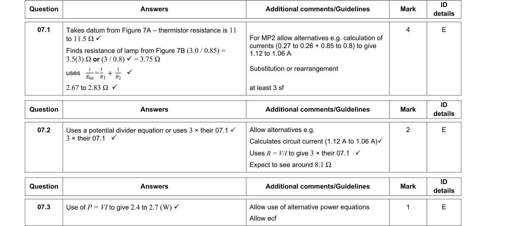
If a device (a load) with resistance $R_L$ is connected across $R_2$, it is in parallel with $R_2$. The combined resistance of the lower part falls, so $V_{\text{out}}$ decreases. The effect is small only if $R_L \gg R_2$. This is why a voltmeter used to measure $V_{\text{out}}$ should have a very high resistance.
Summary
- $V_{\text{out}} = V_{\text{in}} \dfrac{R_2}{R_1 + R_2}$; the p.d. is shared in the ratio of the resistances.
- Variable resistors give an adjustable output; a slider across the whole supply gives 0 V to $V_{\text{in}}$.
- LDR: resistance falls as light increases. NTC thermistor: resistance falls as temperature rises.
- A load across the output lowers $V_{\text{out}}$ unless its resistance is very large.