I–V characteristics
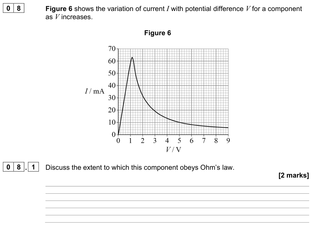
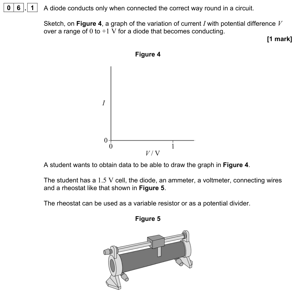
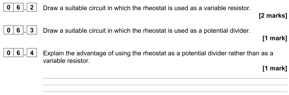
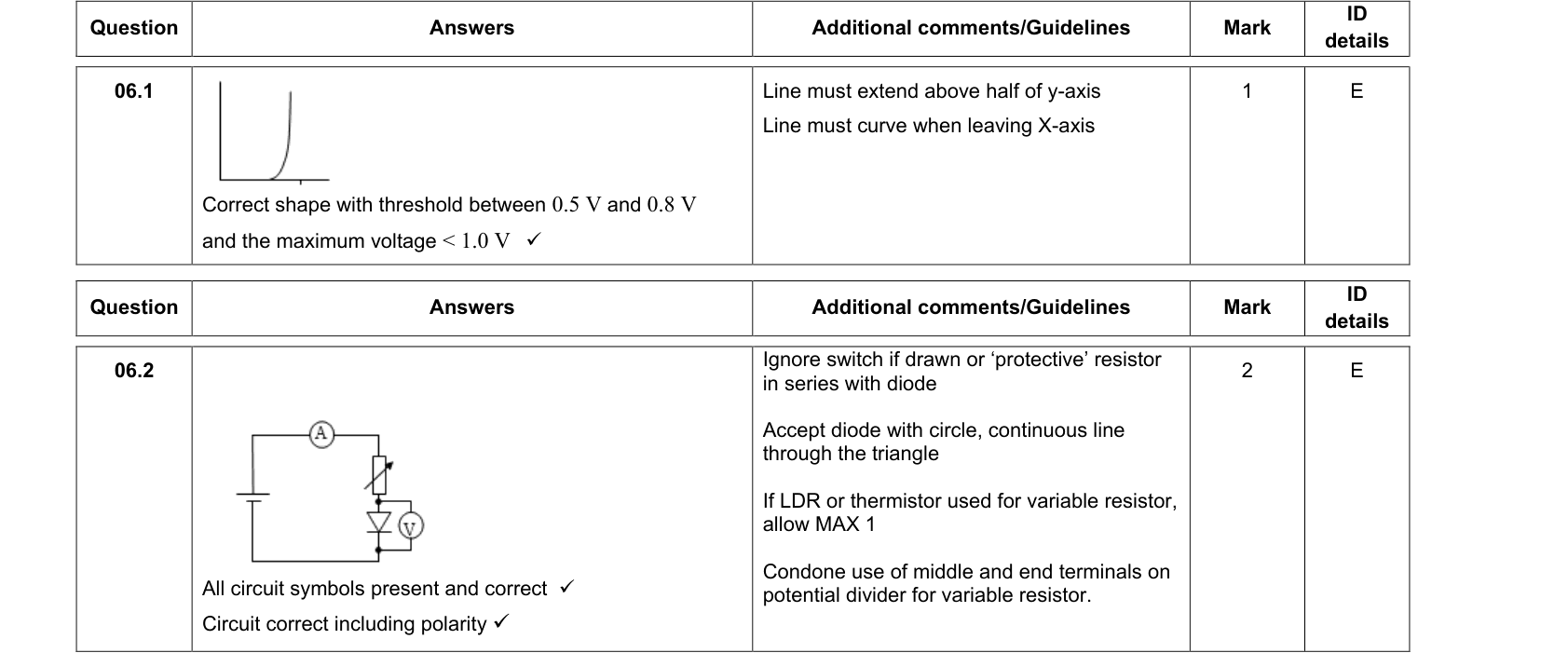
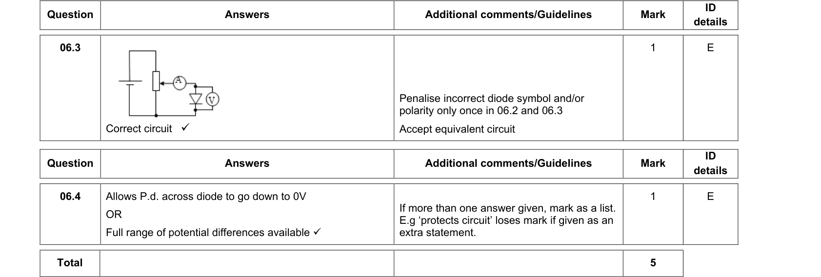
An I–V characteristic is a graph showing how the current through a component varies with the potential difference across it. It is obtained with a variable supply (or a potential divider), an ammeter in series and a voltmeter in parallel, reversing the supply to get negative values.
Watch the axes
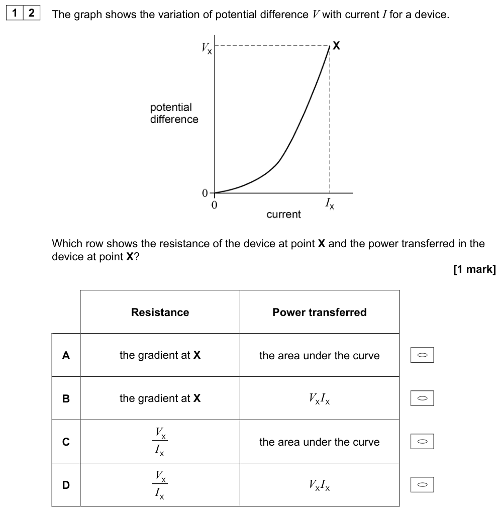
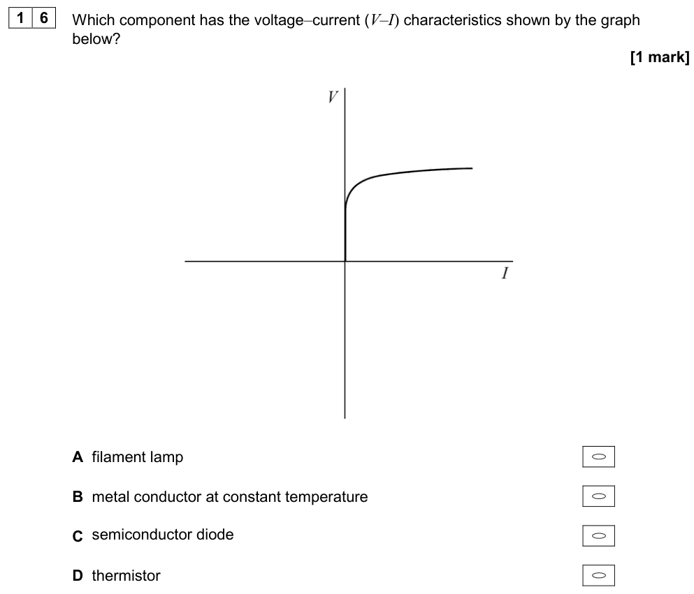
Questions may put either $I$ or $V$ on the horizontal axis. Always check. On an $I$–$V$ graph (I vertical) a steeper line means a smaller resistance. On a $V$–$I$ graph (V vertical) a steeper line means a larger resistance.
Ohmic conductors and Ohm's law
Ohm's law
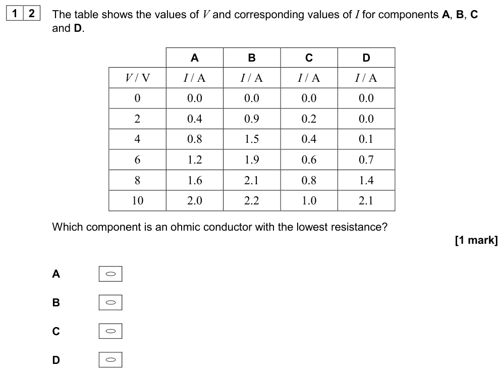
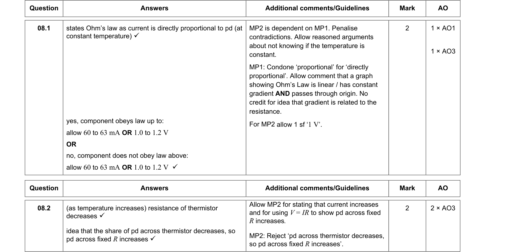
For a metallic conductor at constant temperature (and other constant physical conditions), the current is directly proportional to the potential difference: $I \propto V$.
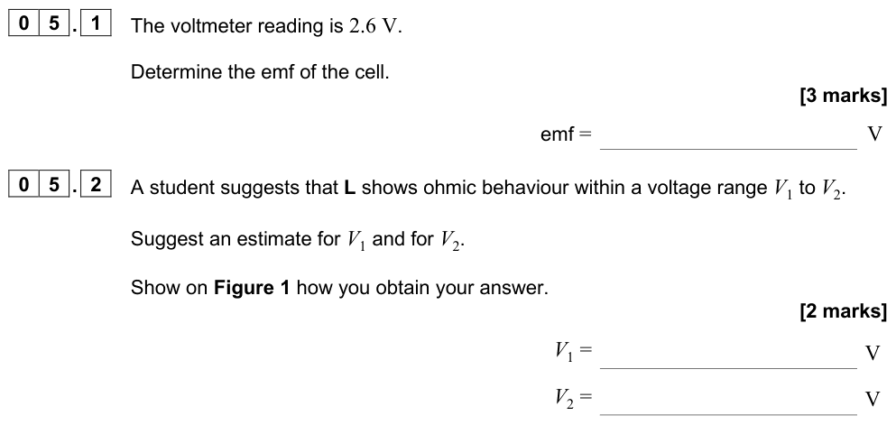
Ohm's law is a special case. It applies only to ohmic conductors under constant conditions.
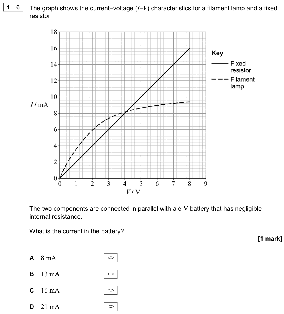
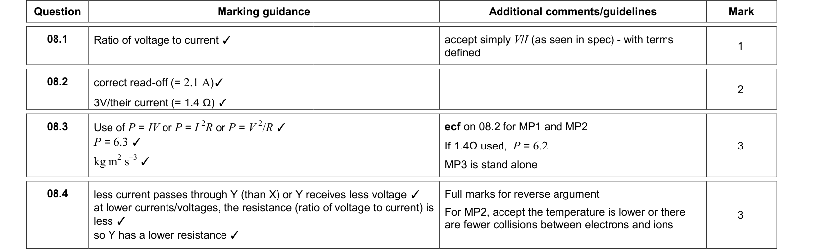
The I–V graph of an ohmic conductor (e.g. a resistor at constant temperature) is a straight line through the origin. The resistance is constant and equal to $V/I$ (the inverse of the gradient on an I–V graph). The graph is the same for both directions of current.
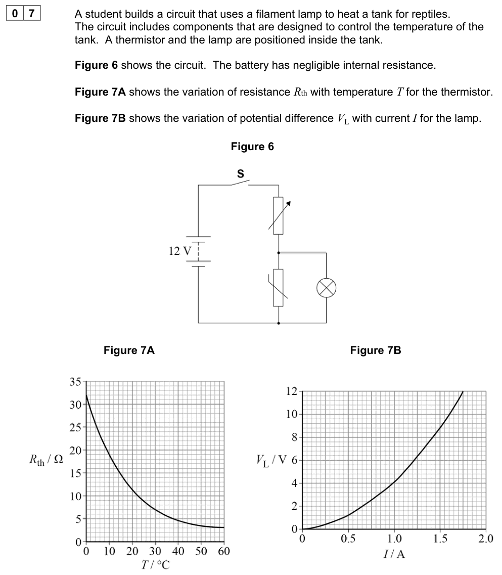
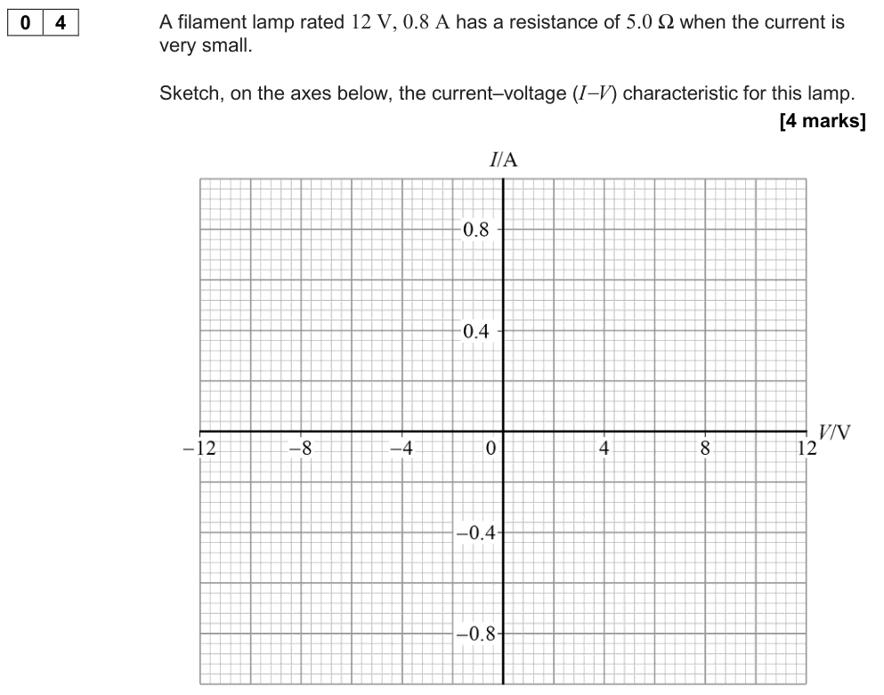
Filament lamp
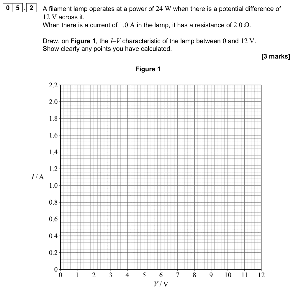
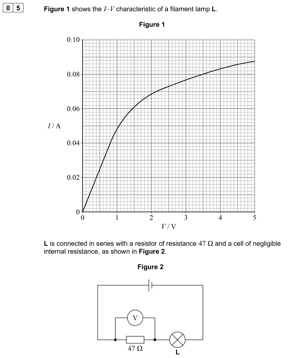
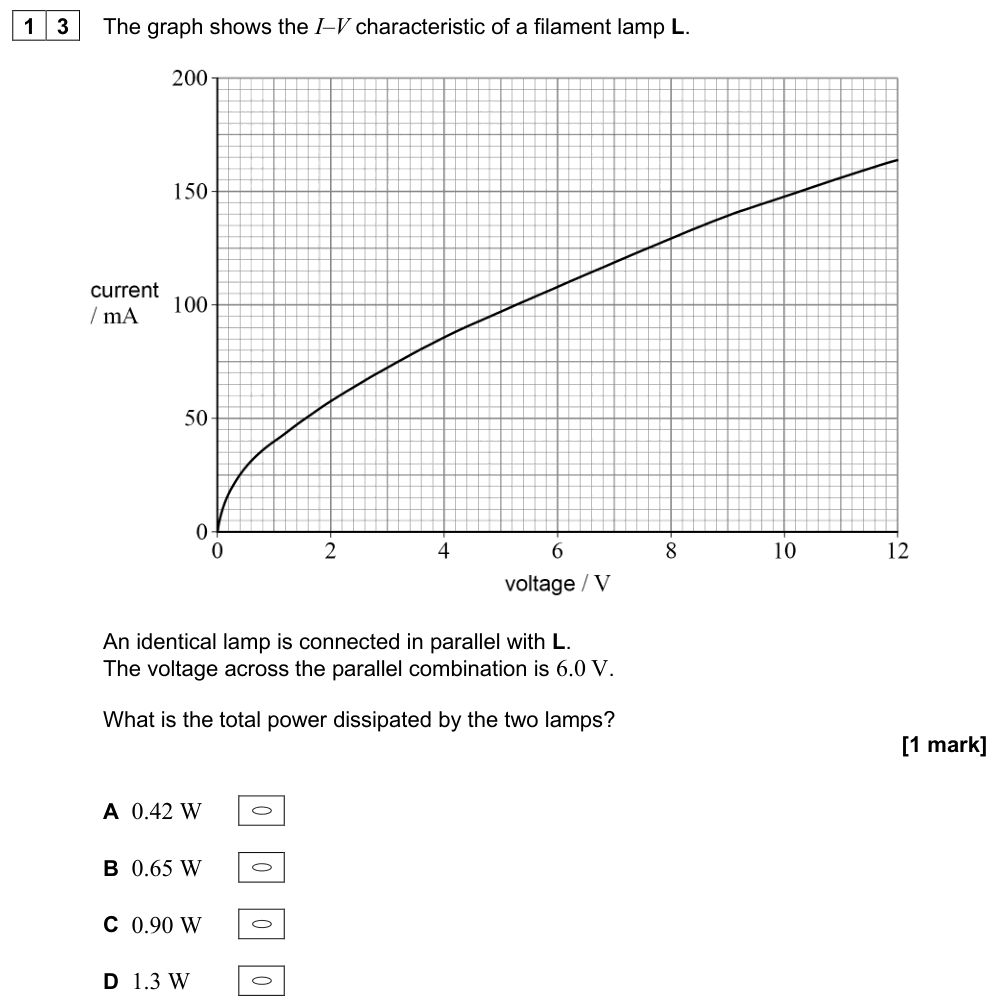
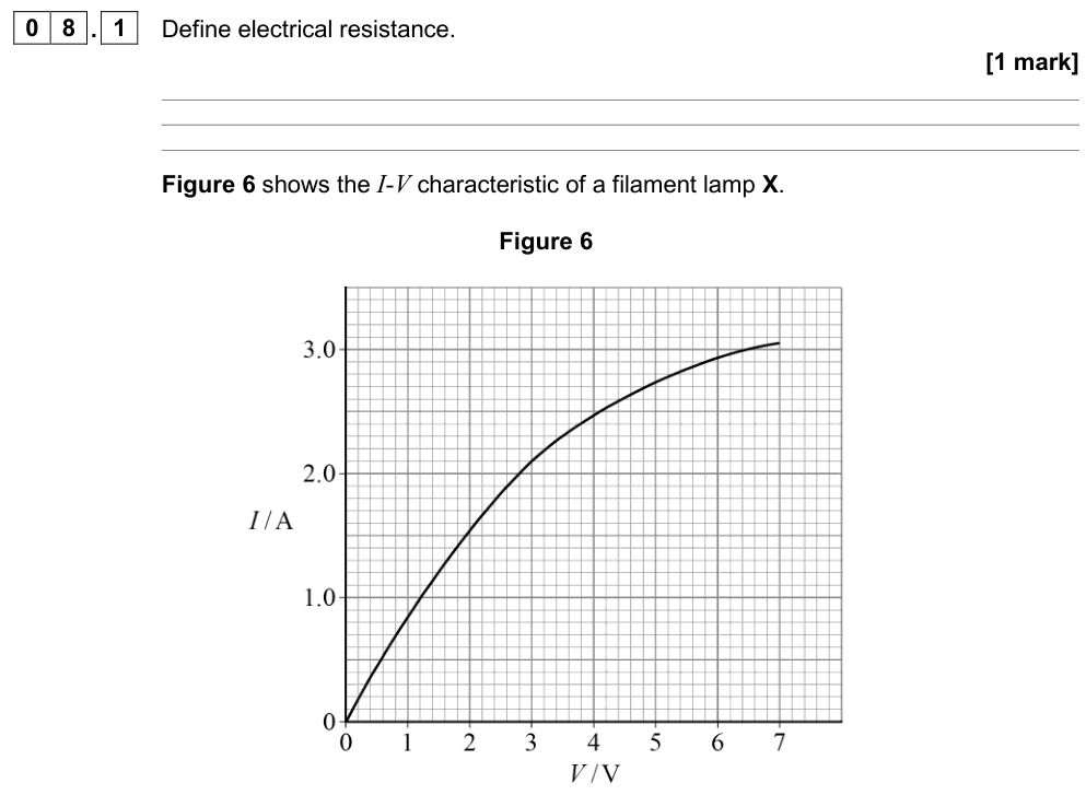
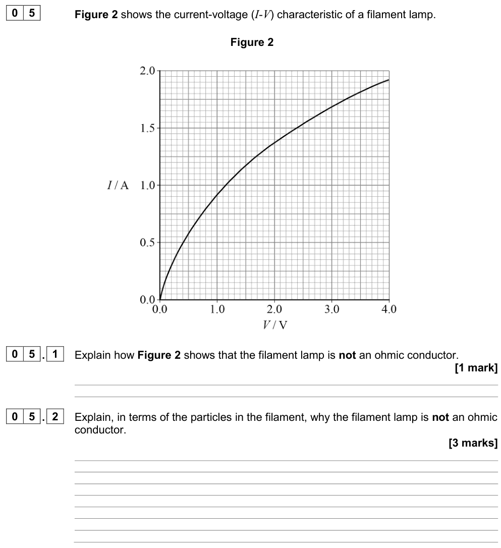
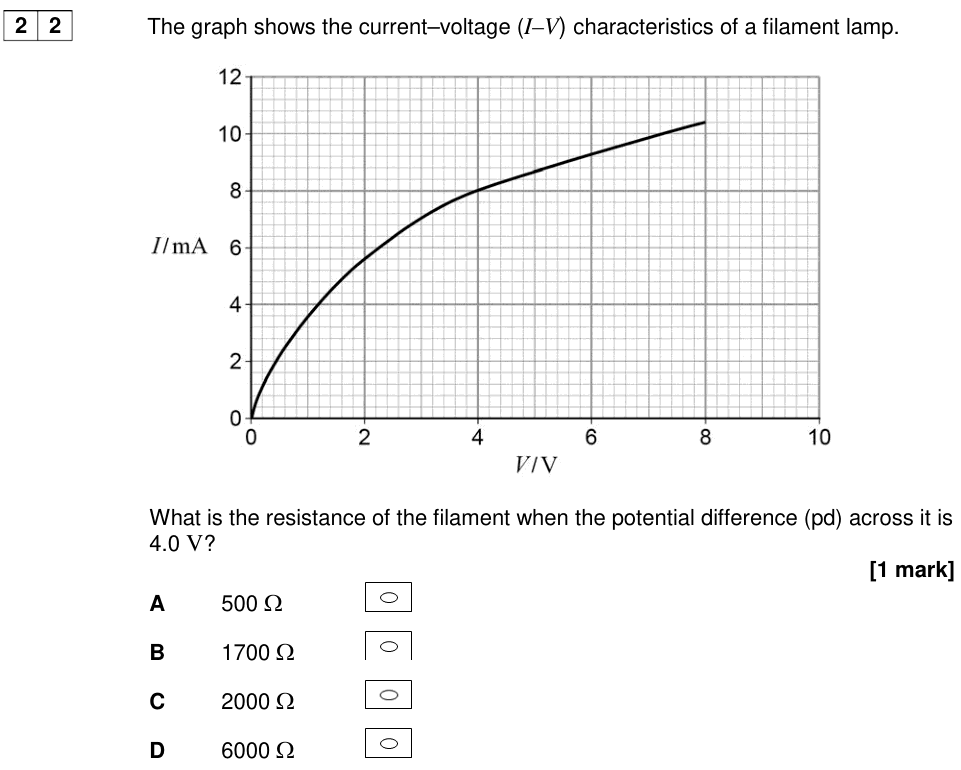
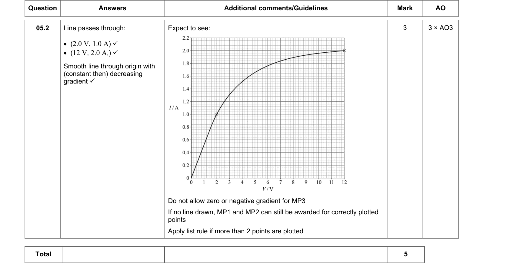
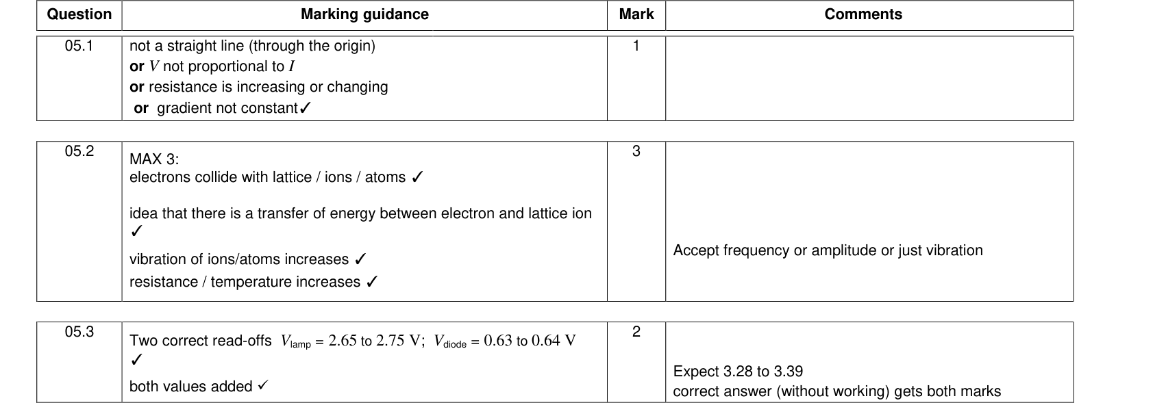
The graph for a filament lamp is a curve that gets less steep as the p.d. increases (in both directions). The resistance increases as the current increases.
Explanation:
- As the current increases, more energy is transferred to the filament per second, so its temperature rises.
- The metal ions in the filament vibrate with greater amplitude.
- The free electrons collide more often with the ions, so it is harder for charge to flow. The resistance increases.
The graph is symmetrical: reversing the p.d. gives the same size of current in the opposite direction.
Semiconductor diode
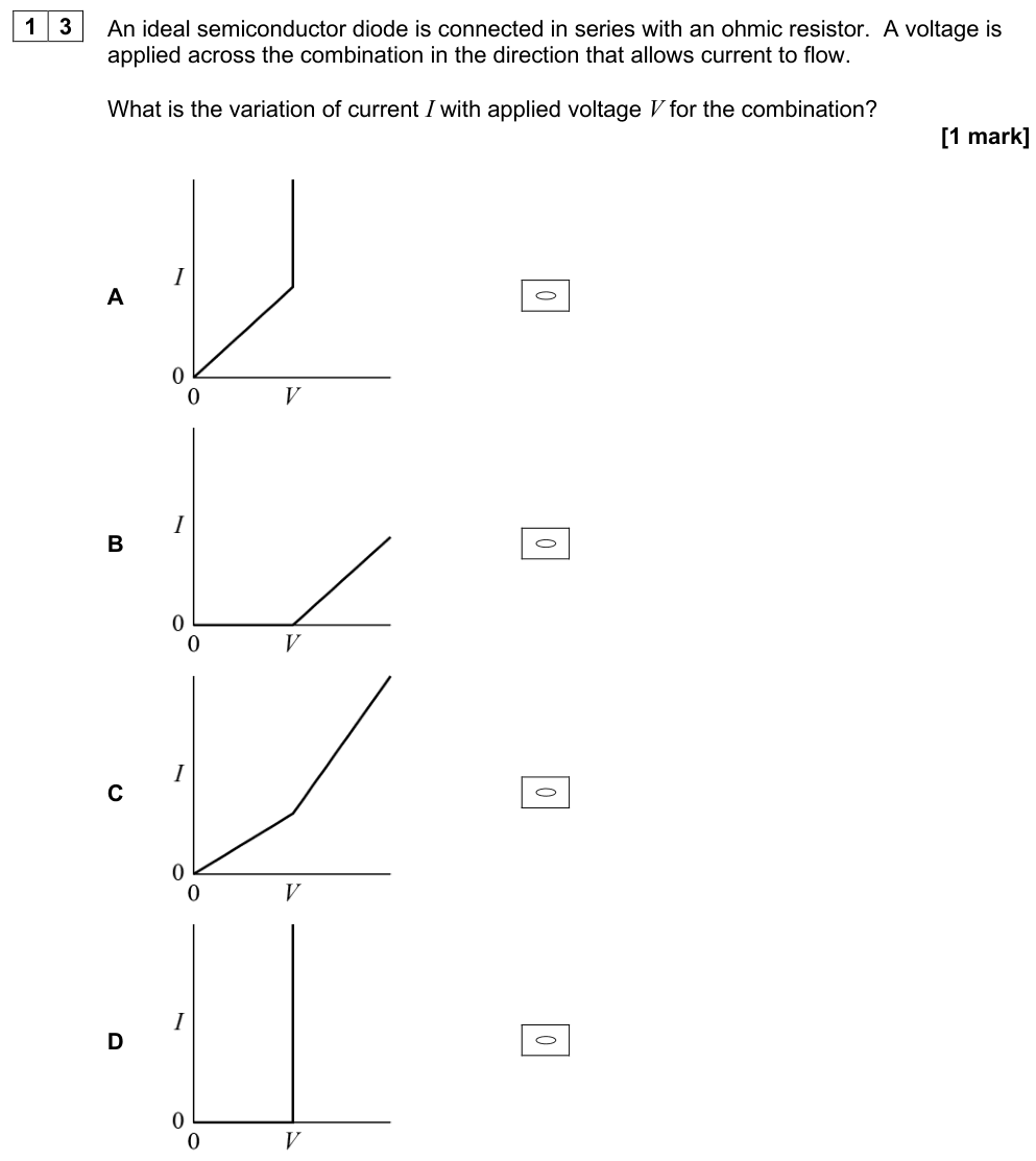
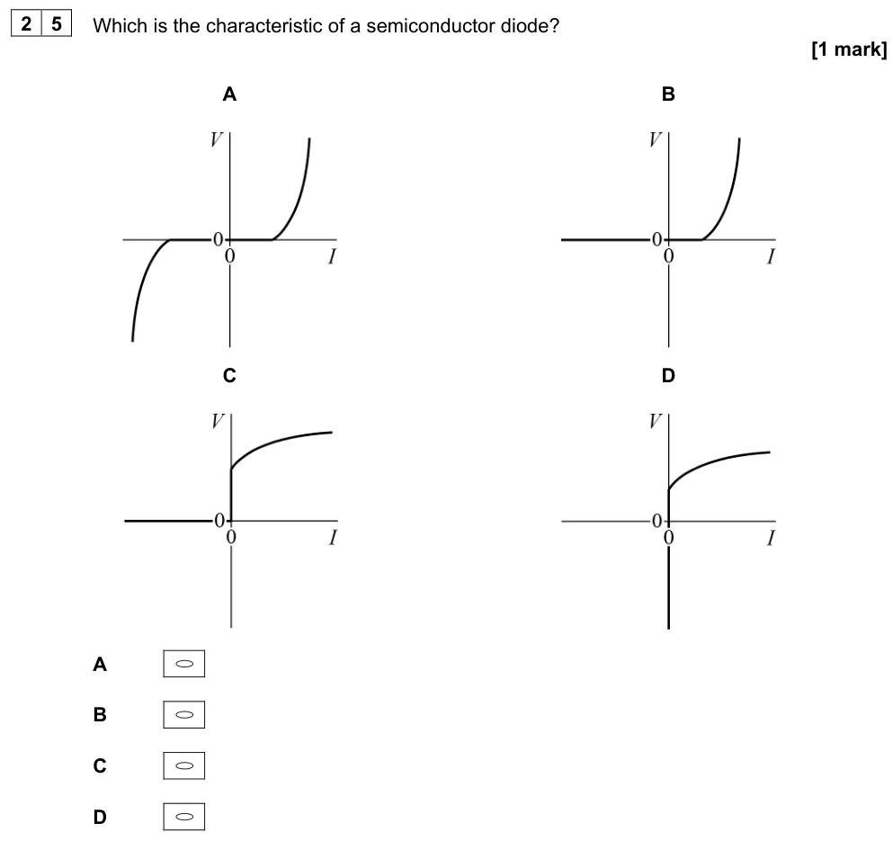
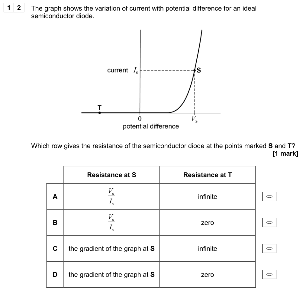
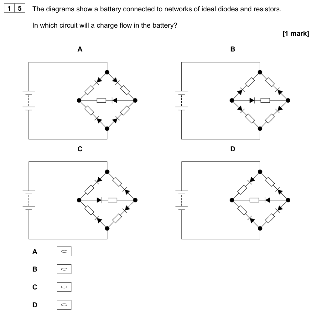
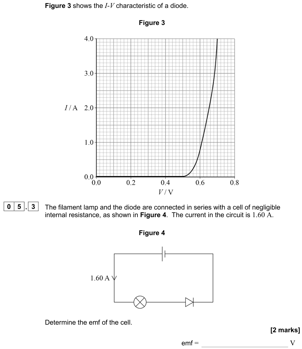
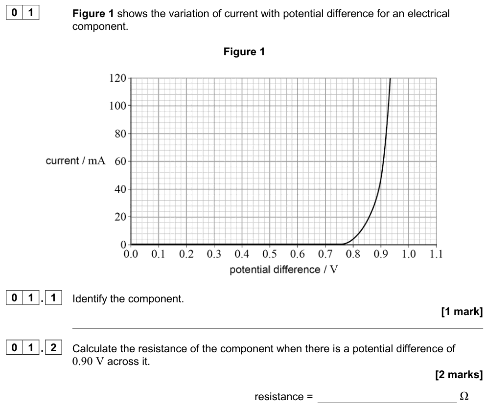
A diode allows current to flow easily in one direction only (the forward direction, in the direction of the arrow in the circuit symbol).
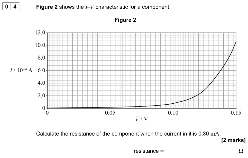
- Forward bias: almost no current until the p.d. reaches the threshold voltage (about 0.6 V for a silicon diode). Above this the current rises rapidly and the resistance becomes very small.
- Reverse bias: the resistance is extremely high and the current is effectively zero (until a very large breakdown voltage).
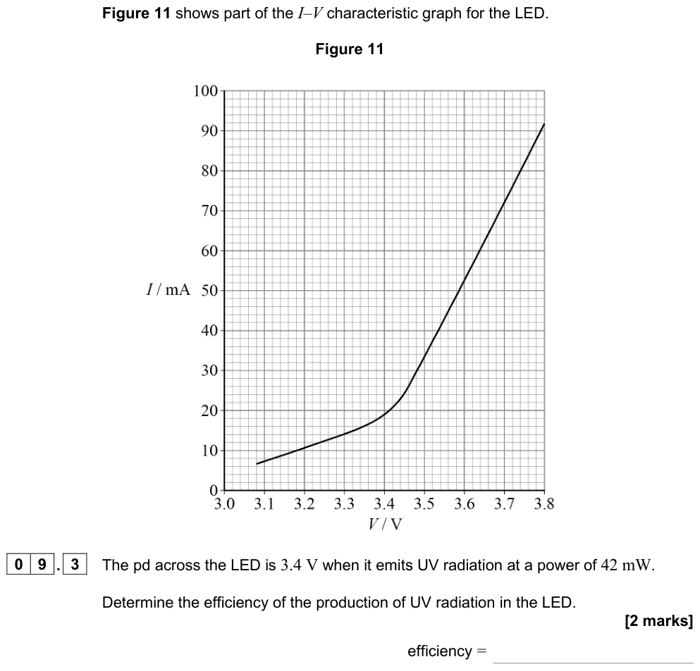
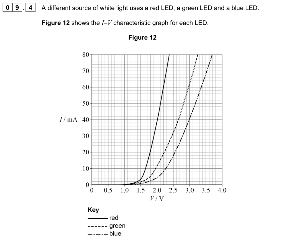
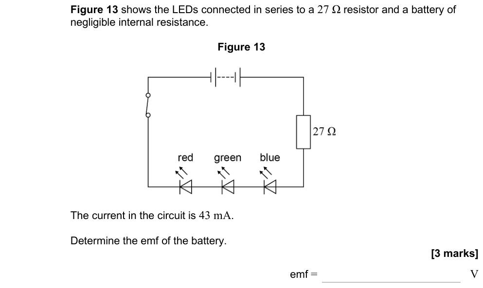
A light-emitting diode (LED) behaves in the same way but has a larger threshold voltage (about 1.5–3 V depending on its colour) and emits light when it conducts.
Working out resistance from a graph
Resistance at a point
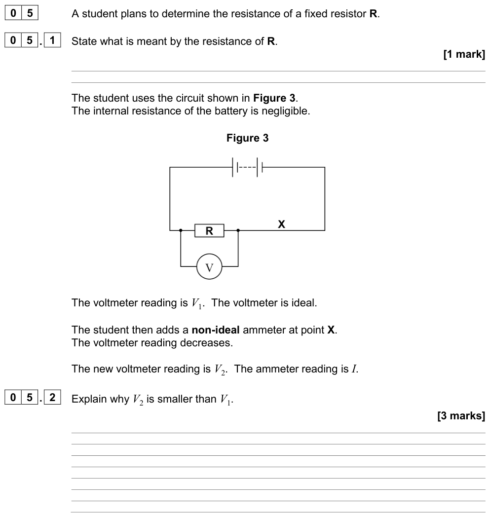
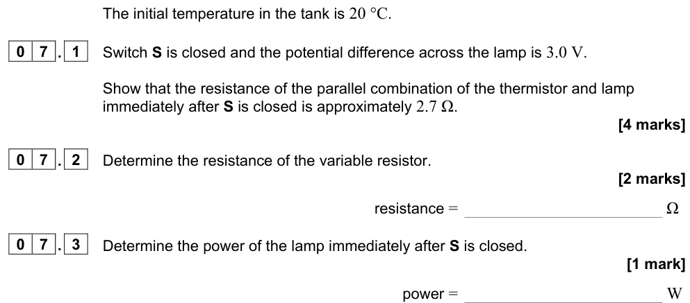
$$R = \frac{V}{I}$$
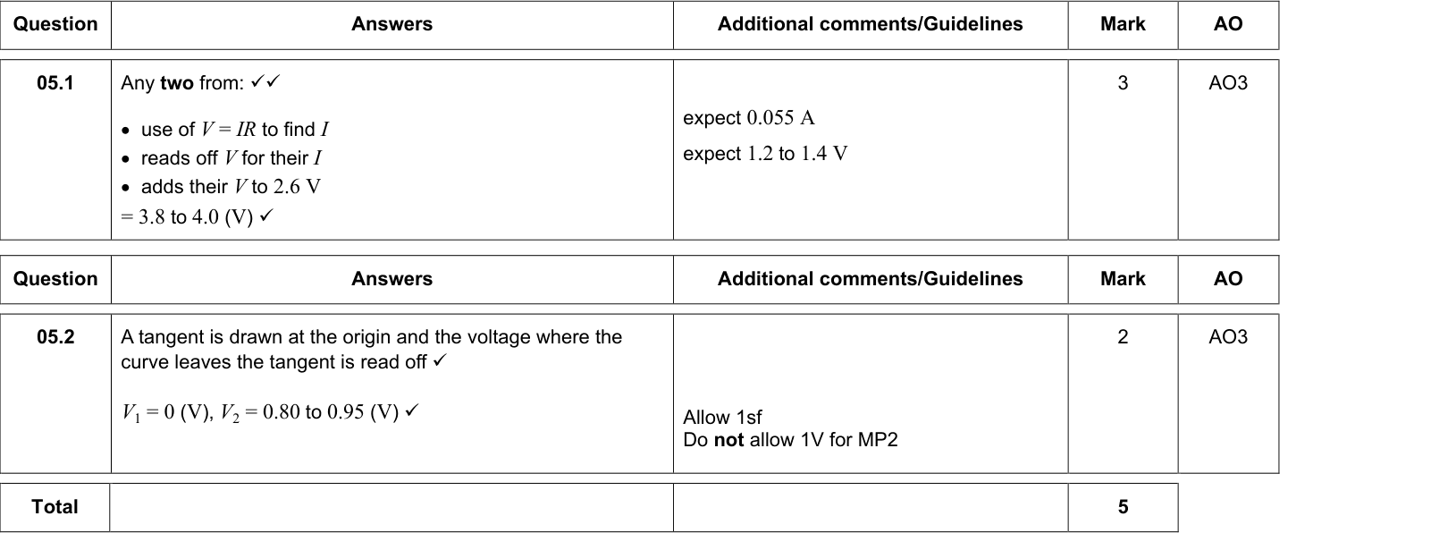
Read $V$ and $I$ at the point and divide. For a curved graph, do not use the gradient (or the gradient of a tangent). The gradient gives how the current changes with p.d., not the resistance.
Worked example: lamp in a circuit
A filament lamp's I–V graph passes through (6.0 V, 0.50 A) and (12.0 V, 0.75 A).
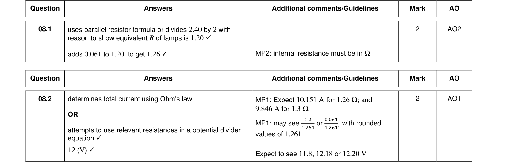
At 6.0 V: $R = 6.0/0.50 = 12\ \Omega$. At 12.0 V: $R = 12.0/0.75 = 16\ \Omega$. The resistance has increased because the filament is hotter.
Worked example: components in series
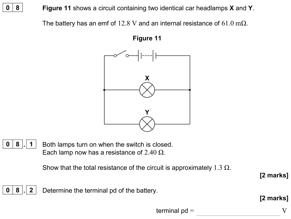
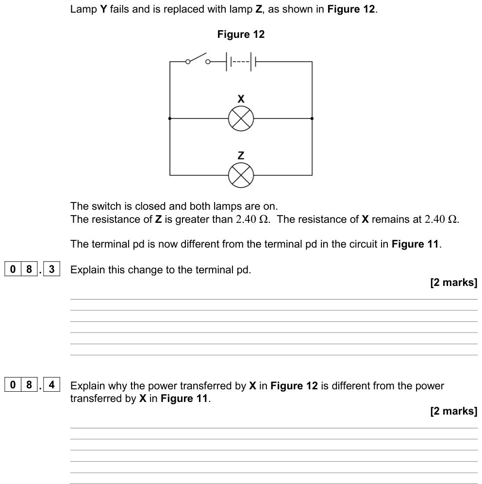
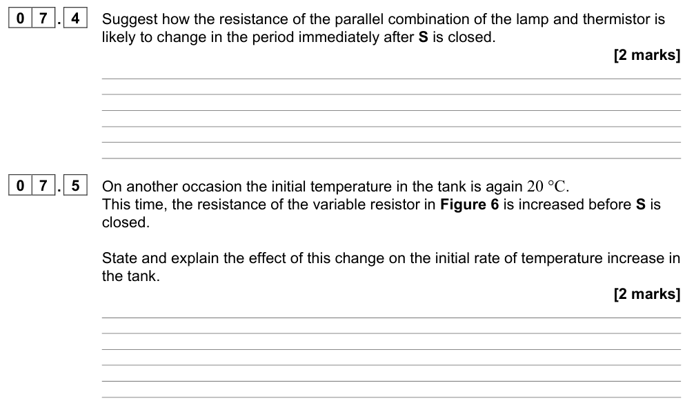
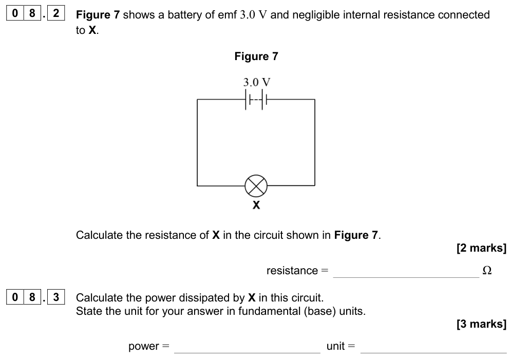
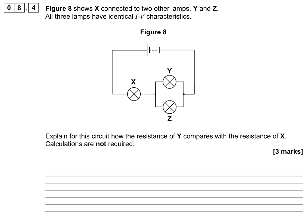
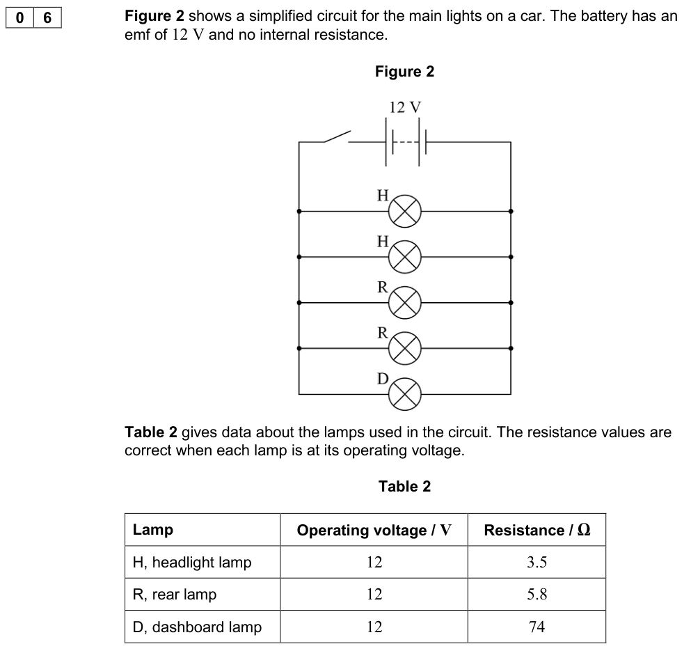
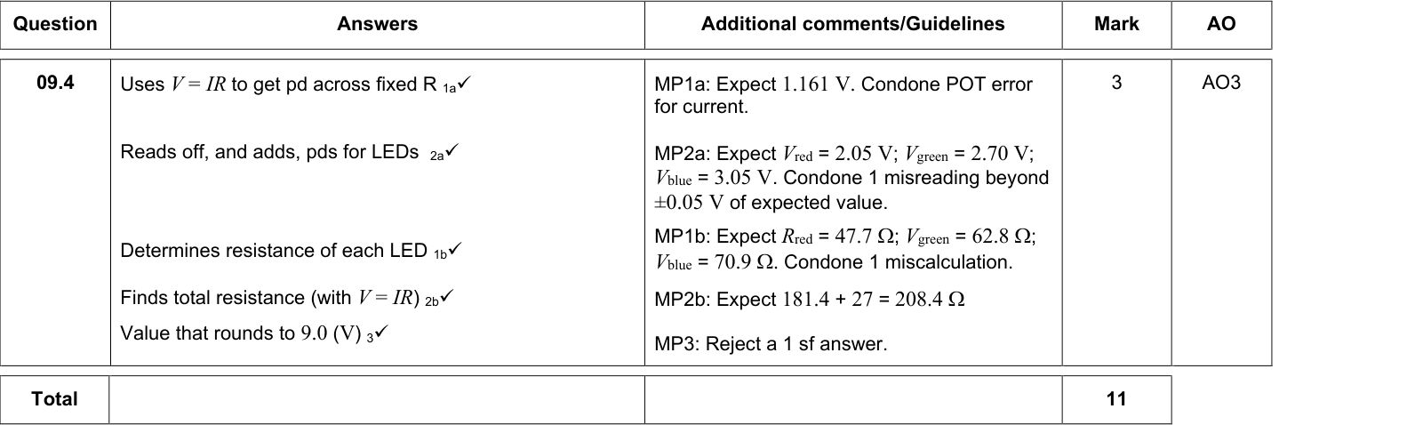
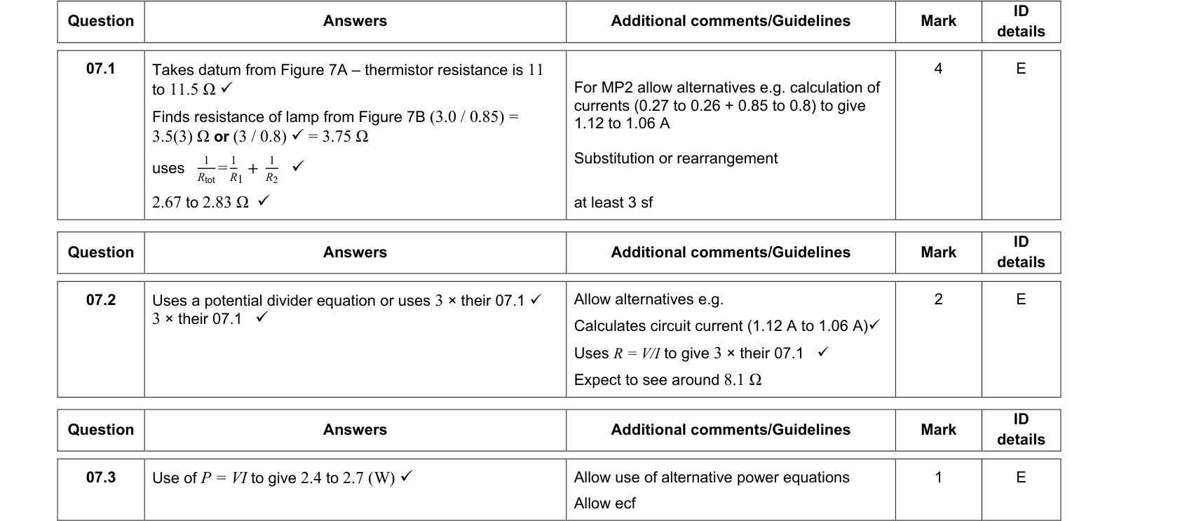
A diode and a resistor are connected in series. The current is the same in both, so to find the supply p.d. for a given current, add the p.d.s read off each characteristic at that current. For components in parallel, the p.d. is the same and the currents add.
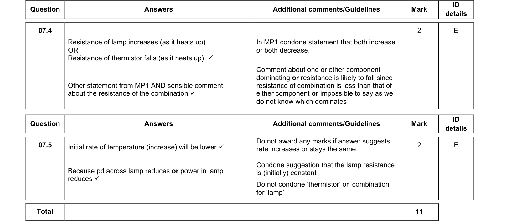
Summary
- Ohmic conductor: straight line through the origin; $I \propto V$ at constant temperature (Ohm's law).
- Filament lamp: curve; resistance rises with current because the hotter filament's ions vibrate more.
- Diode: conducts in the forward direction above about 0.6 V; very high resistance in reverse.
- Resistance at a point $= V/I$, not the gradient.